
Paint spraying device for part machining

A technology for parts and paint tubes, applied in the field of painting devices for parts processing, can solve the problems of being easily inhaled by operators, not being able to drop paint, and the amount of paint that cannot be used, so as to improve the protection effect and reduce the amount of waste. , the effect of increasing accuracy

Inactive Publication Date: 2021-08-03
AVIC POWER ZHUZHOU AVIATION PARTS MFG
View PDF9 Cites 0 Cited by
  • Summary
  • Abstract
  • Description
  • Claims
  • Application Information

AI Technical Summary

Problems solved by technology

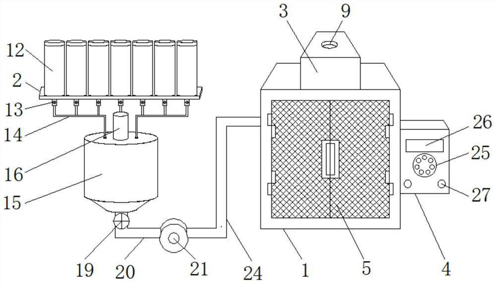
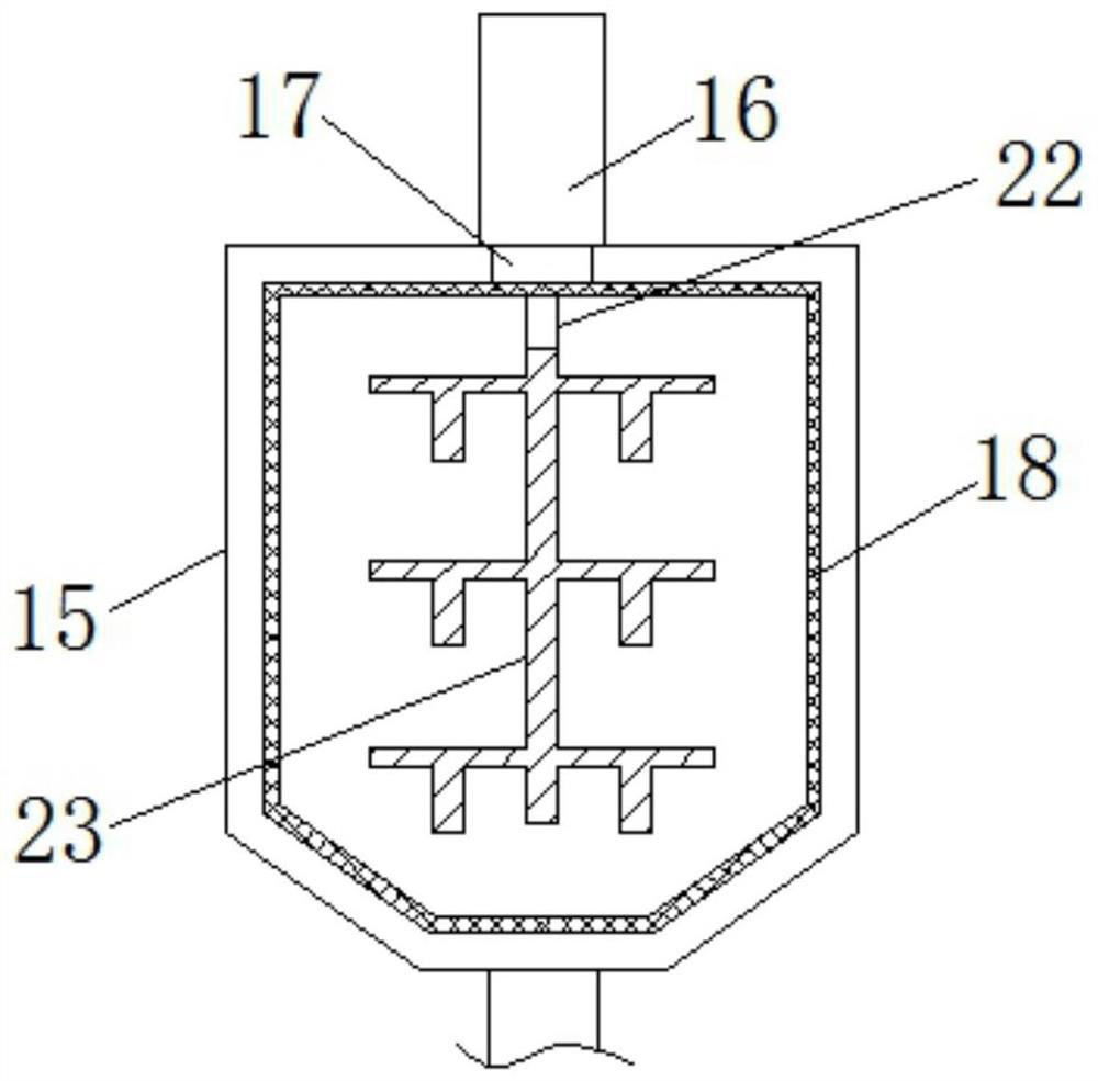
[0004] At present, there are still some deficiencies in the existing paint spraying device for parts processing, for example; The speed of the paint color is relatively low when debugging, and the amount of paint used cannot be controlled. The paint release is prone to excessive or too little phenomenon, which increases the waste of paint when the paint spraying device paints the parts. amount, and the existing paint spraying device for parts processing cannot allow the paint attached to the inner wall of the mixing tank and the mixing rod to fall off by itself. The accuracy of the paint color is so high that the operator needs to clean up the paint attached to the inside of the mixing tank. The existing paint spraying device for parts processing does not filter the discharged gas, and the paint gas is easily discharged into the working environment. Inhalation by the operator reduces the protection effect of the spraying device on the environment during use

Method used


Image

  • Paint spraying device for part machining
  • Paint spraying device for part machining
  • Paint spraying device for part machining

Examples


Embodiment Construction

[0027] The following will clearly and completely describe the technical solutions in the embodiments of the present invention with reference to the accompanying drawings in the embodiments of the present invention. Obviously, the described embodiments are only some, not all, embodiments of the present invention.

[0028] In describing the present invention, it should be understood that the terms "upper", "lower", "front", "rear", "left", "right", "top", "bottom", "inner", " The orientation or positional relationship indicated by "outside", etc. is based on the orientation or positional relationship shown in the drawings, and is only for the convenience of describing the present invention and simplifying the description, rather than indicating or implying that the referred device or element must have a specific orientation, so as to Specific orientation configurations and operations, therefore, are not to be construed as limitations on the invention.

[0029] see Figure 1-Fig...


PUM


Abstract

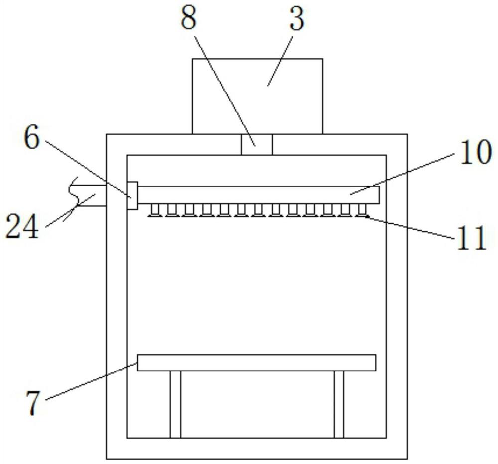
The invention discloses a paint spraying device for part machining. The paint spraying device structurally comprises a paint spraying box and an aluminum alloy mounting plate, the paint spraying box is provided with a gas filtering box, a controller, a door body, a pipeline connector, a placing table and an air outlet, and the gas filtering box is fixedly connected with the upper end of the paint spraying box through screws; and the controller is fixedly connected with the right end of the paint spraying box through screws, the door body is movably connected with the front portion of the paint spraying box through hinges, and the pipeline connector is fixedly connected with the upper left portion of the interior of the paint spraying box through screws. According to the paint spraying device, automatic adjustment can be conducted according to the color needing to be sprayed on a part, the paint color debugging speed is increased, the paint color debugging accuracy is improved, the paint using amount can be controlled, the phenomenon that paint is released too much or too little is avoided, the waste amount of paint when the paint spraying device sprays paint on the part is reduced, and the efficiency of the part in the paint spraying process is improved.

Description

technical field [0001] The invention relates to the technical field of parts processing, in particular to a painting device for parts processing. Background technique [0002] According to the patent 202020467200.9, an automatic painting device for processing small aviation parts is known, including: box body, base, driving motor, connecting pipe, rotating rod, fan blade, fixed plate, driving rod, first electric push rod, belt , a bearing plate, a second electric push rod, a chute, a slide plate, a feeding pipe and a nozzle; the base is set in the box, and grooves are symmetrically opened on the base, and the driving motor is set in the The bottom of the box is located on one side of the base. The utility model fixes the parts between the first electric push rods, and the second electric push rod drives the nozzle to move back and forth, and drives the electric rotation to drive the drive rod to rotate through the belt to realize The parts rotate in a circle, so as to spray...

Claims


Application Information

Patent Timeline
Patent Type & Authority Applications(China)
IPC IPC(8): B05B16/40B05B9/04B05B12/00B05B14/43
CPCB05B9/04B05B12/00B05B14/43B05B16/40
Inventor 彭云杰王熔汤涛罗青
Owner AVIC POWER ZHUZHOU AVIATION PARTS MFG
Learn More