Eureka AIR delivers breakthrough ideas for toughest innovation challenges, trusted by R&D personnel around the world.

A machine vision-based optimal shearing method for hot-rolled strip steel

A technology of hot-rolled strip steel and machine vision, which is applied in the direction of metal rolling, metal rolling, rolling mill control devices, etc., can solve the problems of inability to effectively realize detection, inability to determine the cutting length, and reduce the working efficiency of the rolling mill. Increased cutting loss rate, fast measurement speed, improved production efficiency and product quality

Active Publication Date: 2022-04-22
UNIV OF SCI & TECH BEIJING
View PDF0 Cites 0 Cited by
  • Summary
  • Abstract
  • Description
  • Claims
  • Application Information

AI Technical Summary

Problems solved by technology

[0003] The traditional strip end shape detection uses offline and manual methods, which takes a long time to sample, is labor intensive, and has poor real-time information, which cannot effectively realize the detection and reduce the working efficiency of the rolling mill.
At the same time, the flying shear system in the traditional hot rolling production line often adopts a fixed-length shearing system. Its inherent disadvantage is that the shearing length cannot be determined according to the shape of the head and tail of the strip, resulting in low shearing accuracy, and the shearing length varies from time to time.
In order to prevent dirty cutting, the operator often enlarges the cutting length artificially, which will easily cause an increase in the cutting loss and bring unnecessary waste

Method used

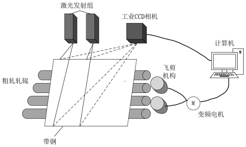
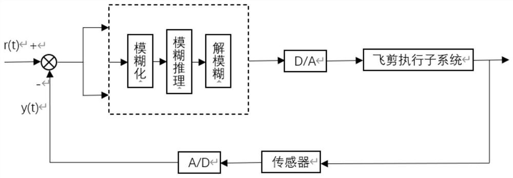
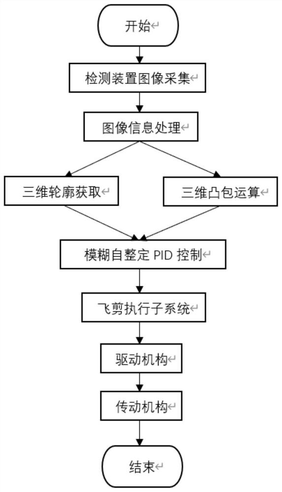

Image

  • A machine vision-based optimal shearing method for hot-rolled strip steel
  • A machine vision-based optimal shearing method for hot-rolled strip steel
  • A machine vision-based optimal shearing method for hot-rolled strip steel

Examples


Embodiment Construction

[0036] In order to make the object, technical solution and advantages of the present invention clearer, the present invention will be further described in detail below in conjunction with the accompanying drawings and embodiments. It should be understood that the specific embodiments described here are only used to explain the present invention, not to limit the present invention.

[0037] On the contrary, the invention covers any alternatives, modifications, equivalent methods and schemes within the spirit and scope of the invention as defined by the claims. Further, in order to make the public have a better understanding of the present invention, some specific details are described in detail in the detailed description of the present invention below. The present invention can be fully understood by those skilled in the art without the description of these detailed parts.

[0038] An embodiment of the present invention provides a machine vision-based method for optimizing th...


PUM


Abstract

The invention belongs to the field of hot-rolled strip steel flying shear control engineering and relates to a machine vision-based optimal shearing method for hot-rolled strip steel. The method is mainly combined with the principle of machine vision to conduct non-contact measurement of the deformation of the strip end caused by rough rolling on the hot rolling production line, and optimize the control of the flying shear system through a fuzzy self-tuning PID controller, including the following operations Steps: 1) image acquisition of strip end; 2) image information processing; 3) three-dimensional contour acquisition; 4) three-dimensional convex hull calculation; 5) fuzzy self-tuning PID controller decision-making; ) actuator for shearing. The invention is based on a machine vision detection system, combined with an image processing unit to obtain the three-dimensional profile of the steel strip end, and controls the flying shear mechanism through a fuzzy self-tuning PID controller, and the shear mechanism performs precise cutting after receiving a signal sent by the controller. The invention realizes the online optimization of the hot-rolled steel strip flying shear system through the closed-loop control structure.

Description

technical field [0001] The invention belongs to the field of hot-rolled strip steel flying shear control engineering and relates to a machine vision-based optimal shearing method for hot-rolled strip steel. Background technique [0002] In the hot rolling production process, after the strip steel billet is rolled by the rough rolling unit, due to the uneven pressure of the rough roll or the influence of the environment, the end of the strip is prone to deformation. In order to ensure the stability of subsequent production, before entering the finish rolling unit Strip ends are required to be cut off. [0003] The traditional strip end shape detection uses offline and manual methods. The sampling time is long, the labor intensity is high, and the real-time information is poor. The detection cannot be effectively realized and the working efficiency of the rolling mill is reduced. At the same time, the flying shear system in the traditional hot rolling production line often ad...

Claims


Application Information

Patent Timeline
Patent Type & Authority Patents(China)
IPC IPC(8): B21B38/02B21B37/00B21B15/00
CPCB21B38/02B21B37/00B21B15/0007B21B2015/0014
Inventor 张飞刘心爽项晓菲张勇军邓能辉杨朝霖郭杨肖雄
Owner UNIV OF SCI & TECH BEIJING
Why Eureka
Eureka Blog
Learn More