
Chassis underframe welding integrated application system and welding method

A welding method and chassis technology, applied in welding equipment, resistance welding equipment, manufacturing tools, etc., can solve problems affecting welding quality, welding deformation, and poor product consistency, so as to improve welding efficiency and quality, and reduce welding deformation Effect

Active Publication Date: 2021-08-03
GUANGXI UNIV +1
View PDF6 Cites 0 Cited by
  • Summary
  • Abstract
  • Description
  • Claims
  • Application Information

AI Technical Summary

Problems solved by technology

[0002] The electric sweeper is a vacuum suction type floor sweeper used for cleaning the ground. There is a sweeping brush in front of the car, which guides the cleaned garbage to the suction nozzle assembly. The garbage is sucked by the suction nozzle assembly and delivered to the vehicle through the connected pipe. In the vacuum garbage bin at the rear, the frame of the electric sweeper is divided into a hinged front frame and a rear frame. Manufacturing involves a lot of welding work, the amount of welding is large, and the welding difficulty is relatively large. The selection of the welding sequence will affect the quality of the welding. If the correct welding sequence is not selected, it will largely cause deformation of the frame and affect the quality of the welding. Welding quality, the product consistency after welding is poor, resulting in welding deformation and installation difficulties, affecting subsequent assembly, resulting in a low pass rate of finished products

Method used


Image

  • Chassis underframe welding integrated application system and welding method
  • Chassis underframe welding integrated application system and welding method
  • Chassis underframe welding integrated application system and welding method

Examples


Embodiment

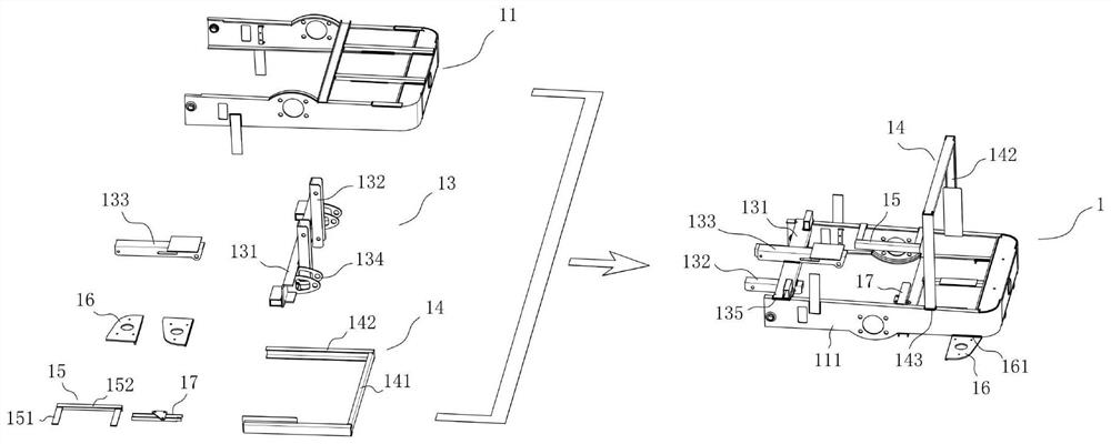
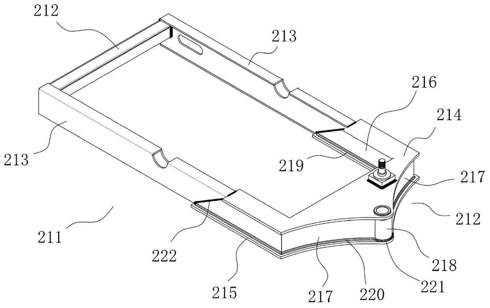
[0037] see Figure 7 As shown, the present invention discloses an integrated application system for chassis chassis welding, which includes a welding robot 3, a slide rail 5, a robot base 6, a positioner 4, and a turning table 7 for installing workpieces to be welded. The rail 5 is parallel to the length direction of the positioner 4, and a slidable robot base 6 is installed on the slide rail 5, and the welding robot 3 is installed on the robot base 6 and driven by the robot base 6 to move along the direction of the slide rail 5 Move to different positions, the two ends of the turning table 7 are connected to the rotary shaft of the positioner 4, and the turning machine 4 controls the turning table 7 to tilt at different processing positions, which is convenient for the welding robot 3 to perform welding operations.

[0038] The present invention also provides a welding method for the underframe of the vehicle chassis, which specifically includes the following steps:

[0039]...


PUM


Abstract

The invention discloses a chassis underframe welding integrated application system and a welding method. The welding method comprises the following steps that 1, all scattered workpieces of a front frame are respectively welded into assemblies, and then all the assemblies are welded into the front frame in a manner of conducting manual spot welding and robot full welding in sequence; 2, all scattered workpieces of a rear frame are welded into assemblies respectively, and then all the assemblies are welded into the rear frame in a manner of conducting manual spot welding and robot full welding in sequence; and 3, the front frame and the rear frame after full welding of a robot are checked, and repair welding is manually conducted on special dead angle positions where a welding gun of the robot cannot reach. According to a welding process provided by the invention, the frame welding deformation can be reduced, the welding method is suitable for welding a chassis underframe of an electric sweeper, and the frame welding efficiency and welding quality are further improved.

Description

technical field [0001] The invention relates to the technical field of vehicle frame welding, in particular to a chassis welding system and method for an electric floor sweeping vehicle. Background technique [0002] The electric sweeper is a vacuum suction type floor sweeper used for cleaning the ground. There is a sweeping brush in front of the car, which guides the cleaned garbage to the suction nozzle assembly, and the garbage is sucked by the suction nozzle assembly and delivered to the vehicle through the connected pipe. In the vacuum garbage bin at the rear, the frame of the electric sweeper is divided into a hinged front frame and a rear frame. Manufacturing involves a lot of welding work, the amount of welding is large, and the welding difficulty is relatively large. The selection of welding sequence will affect the quality of welding. If the correct welding sequence is not selected, it will largely cause deformation of the frame and affect the quality of welding. ...

Claims


Application Information

Patent Timeline
IPC IPC(8): B23K11/11B23K11/36B23K31/02B25J11/00
CPCB23K11/11B23K11/36B23K31/02B25J11/00
Inventor 梁旭斌刘冠良李睿亮潘海鸿蓝敏莫俊飞潘寿岭黄恒放张琦伟
Owner GUANGXI UNIV
Learn More