Cutting waste collecting device of numerical control machine tool

A waste collection, CNC machine tool technology, applied in positioning devices, metal processing machine parts, clamping and other directions, can solve problems such as handling difficulties, and achieve the effect of convenience and stability

Active Publication Date: 2021-08-03
江苏函杰机床有限公司
View PDF7 Cites 1 Cited by
  • Summary
  • Abstract
  • Description
  • Claims
  • Application Information

AI Technical Summary

Problems solved by technology

[0003] CNC machine tools are mainly divided into cutting machine tools, drilling machine tools, grinding machine tools, etc. according to their different functions. Among them, when preparing some large plates, it is often necessary to use large cutting machine tools to process the plates. Various types of machine tools are used During the processing of the initial plate, a large amount of metal waste will appear, and these wastes will accumulate on the bed of the machine tool, and the waste falling on the bed will mix with the coolant, causing the problem of difficult subsequent processing

Method used


Image

  • Cutting waste collecting device of numerical control machine tool
  • Cutting waste collecting device of numerical control machine tool
  • Cutting waste collecting device of numerical control machine tool

Examples


Embodiment 1

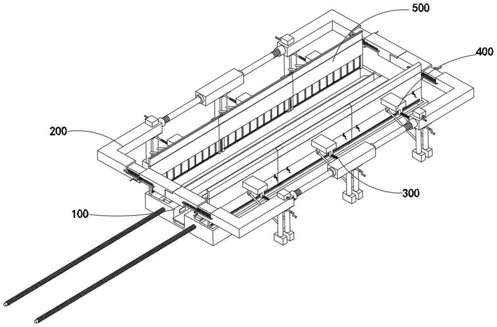
[0052] combine figure 1 , 3 , 4, 7 and 9, the CNC machine tool cutting waste collection device provided by the present invention includes a sheet metal fixture 100, a restraint assembly 200, a length adjustment mechanism 300, a fixation assembly 400 and a material guide mechanism 500, wherein the restraint assembly 200 Located above the sheet metal fixture 100, the length adjustment mechanism 300 is installed in the restraint assembly 200, and the fixation assembly 400 is fixedly installed on the restraint assembly 200 and the length adjustment mechanism 300 through the vertical pile 410 inside it, and the material guide mechanism 500 is installed On the plenum block 450 inside the fixed assembly 400 .

[0053] The sheet metal fixture 100 includes a base 110, a partition 120, a compression assembly 130, a compression assembly 111, an anti-slip assembly 112, and a slide bar assembly 113, while the constraint assembly 200 includes a main control 210, a handle 220, a first adapt...

Embodiment 2

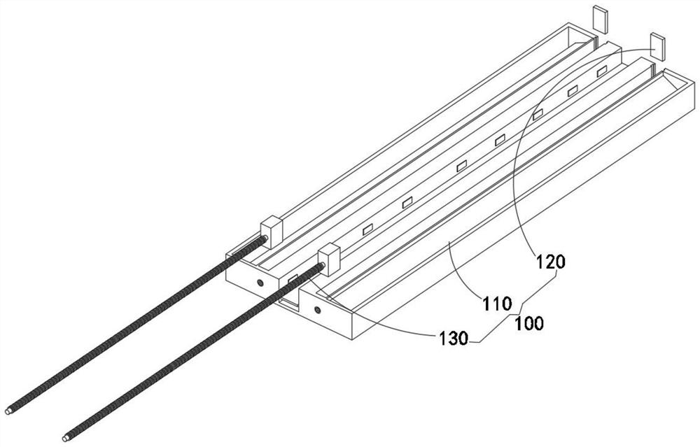
[0058] combine image 3 As shown, on the basis of the first embodiment, by setting the partition plate 120 and the compression assembly 130, when the inside of the two inclined slides is filled with metal scraps, the screw on the compression assembly 130 is used to push the rectangular compact at one end. The extrusion of the metal scraps can make the metal scraps easy to form, thereby realizing the unified treatment of the metal scraps. The metal sheet fixing part 100 also includes a partition 120 inserted in one end of the two inclined slideways and a threaded connection Compression combination 130 at the other end of the two inclined slides.

Embodiment 3

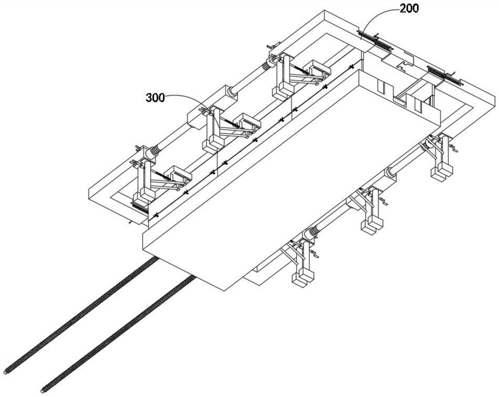
[0060] combine Figure 6 As shown, on the basis of Embodiment 1, a base 310 and a half-screw 320 are set, and one end of the half-screw 320 is fixedly installed inside the base 310. When the base 310 is controlled to rotate, the half-screw 320 will move along the The inner cavity of the main control 210 is rotated so as to realize rapid contraction of the device. The length adjustment mechanism 300 includes a half-screw 320 connected to the inner cavity of the main control 210 and a base 310 installed on the outer end of the half-screw 320 .


PUM


Abstract

The invention discloses a cutting waste collecting device of a numerical control machine tool. The device comprises a metal plate fixing part, a restraining assembly, a length adjusting mechanism, a fixing assembly and a material guiding mechanism, two inclined inner cavity sliding ways are arranged in the metal plate fixing part, the metal plate fixing part comprises a base, and the base comprises a compression assembly, a sliding rod assembly installed at the bottom of the compression assembly and an anti-skid assembly connected to the sliding rod assembly. Two sets of main control pieces are arranged, a first adapter and a second adapter are movably installed on the two sets of main control pieces correspondingly, half screws are installed in the two sets of main control pieces in a matched mode, the first adapter and the second adapter are located outside a plate after being connected in an inserted mode, the contraction of the first adapter and the second adapter on the main control pieces is controlled by controlling cranks on the two sets of main control pieces, so that the device can quickly limit and fix metal plates with different sizes, and the stability of the metal plates in the cutting process is improved.

Description

technical field [0001] The invention relates to the technical field of CNC machine tool cutting waste, in particular to a CNC machine tool cutting waste collection device. Background technique [0002] CNC machine tool is the abbreviation of digital control machine tool. It is also an automatic machine tool equipped with a program control system. In terms of function, it can make plates into standardized products according to the requirements of drawings. [0003] CNC machine tools are mainly divided into cutting machine tools, drilling machine tools, grinding machine tools, etc. according to their different functions. Among them, when preparing some large plates, it is often necessary to use large cutting machine tools to process the plates. Various types of machine tools are used In the process of processing the initial plate, a large amount of metal scrap will appear, and these scraps will gather on the bed of the machine tool, and the scraps falling on the bed will mix w...

Claims


Application Information

Patent Timeline
IPC IPC(8): B23Q11/00B23Q11/08B23Q11/10B23Q3/06
CPCB23Q11/0042B23Q11/08B23Q11/10B23Q3/06
Inventor 于娜
Owner 江苏函杰机床有限公司
Why Eureka
Try Eureka