Rail gnawing prevention walking device self-adaptive to rail gauge and wheel pressure

A walking device, self-adaptive technology, applied in safety devices, walking mechanisms, transportation and packaging, etc., can solve the problems of motor equipment damage, slippage, deviation, etc., to reduce the degree of unbalanced force and avoid three legs.” phenomenon, the effect of preventing rail gnawing

Active Publication Date: 2021-08-03
XIAMEN UNIV
View PDF6 Cites 4 Cited by
  • Summary
  • Abstract
  • Description
  • Claims
  • Application Information

AI Technical Summary

Problems solved by technology

When the "three legs" of the trolley run, the driving ability is reduced, it is easy to slip, and it goes off the rails, causing rail gnawing
[0004] In addition, the dimensional accuracy of the center distance and straightness of the track changes dynamically with temperature and operating conditions. The thermal expansion and contraction of the track and the deformation under the action of external loads will cause the gauge to change, and the two tracks are not on the same level. "Three legs" and the rail-gnawing phenomenon
Regular and long-term rail gnawing will cause great damage to the track, wheels, motors and other related equipment, affecting the safe and stable operation of the trolley, and even leading to major safety accidents

Method used


Image

  • Rail gnawing prevention walking device self-adaptive to rail gauge and wheel pressure
  • Rail gnawing prevention walking device self-adaptive to rail gauge and wheel pressure
  • Rail gnawing prevention walking device self-adaptive to rail gauge and wheel pressure

Examples


Embodiment Construction

[0057] The invention will be further described below with reference to the accompanying drawings and specific embodiments.

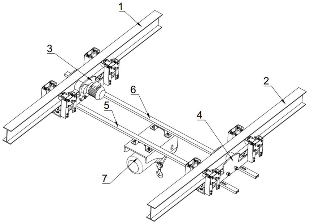
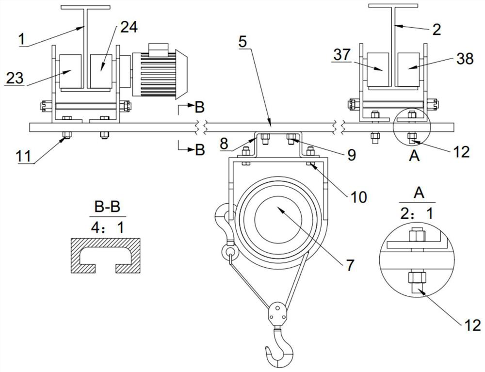
[0058] An anti-rail rail walking device, reference Figure 1 to 11 First orbit 1 and the second track 2, including each other, and the active trails disposed on the first track 1 and the drive train 4 disposed on the second track 2; the active trolley 3 There is also two sliced ​​cross beams from the vehicle 4, respectively, the first belt sliding cross member 5 and the second tide beam 6, the first belt slot beam 5 and the second band slot beam. 6 is also equipped with electric gap 7;

[0059] The active trail 3 is suspended on the first track 1 by the first carrier, and the driven trolley 4 is suspended on the second rail 2 by the second bearing wheel; the active trolley 3 passes through the first bolt group 11 and the belt The hole groove on the chute beam is fixed, the driven trolley 4 is attached to a sliding groove 64 with a sliding groove group 12 by a...


PUM


Abstract

The invention provides a rail gnawing prevention walking device self-adaptive to a rail gauge and wheel pressure. The rail gnawing prevention walking device comprises a first rail, a second rail, a driving trolley and a driven trolley. Two cross beams with sliding grooves are further arranged between the driving trolley and the driven trolley, and electric hoists are further arranged on the cross beams with the sliding grooves. The driving trolley is suspended on the first rail through a first bearing wheel, and the driven trolley is suspended on the second rail through a second bearing wheel. The driving trolley is fixedly connected with hole grooves in the cross beams with the sliding grooves through a first bolt set, and the driven trolley is movably connected with the sliding grooves in the cross beams with the sliding grooves through a double-end stud set. The electric hoists are fixed to a sliding frame through a second bolt set, and the sliding frame is in sliding connection with the sliding grooves through a T-shaped bolt set. The driving trolley is connected with a driving motor and drives the driven trolley to move synchronously through the cross beams with the sliding grooves, and the electric hoists are driven to move synchronously. By means of the technical scheme, potential safety hazards of rail gnawing and derailing of the walking device can be eliminated, and the running reliability and stability of the walking device are improved.

Description

Technical field [0001] The present invention relates to the field of walking devices, and specifically refers to a rail spacing and a rotor-adapted anti-rail traveling device. Background technique [0002] At present, the main, the relative position between the rotation axis of the vehicle, the relative position between the rotation axis and the small frame of the vehicle, and the manufacturing error of the parts such as wheel and gears, assembly error, and worse worse. If the car is driven by two motors, the electrical control line is used to maintain two motor speed constant relationships, and the cost is higher, and due to the difference in electrical control, the power of the motor, the operation of the two-side active wheel cannot be completely Synchronize. If the trolley is driven by a single motor, it is necessary to drive the long drive shaft to drive both the drive wheel, and the lower rigid long drive shaft can also cause the active wheel. The above manufacturing error,...

Claims


Application Information

Patent Timeline
Patent Type & Authority Applications(China)
IPC IPC(8): B66C9/16B66C9/08B66C7/08B66C11/06B66C15/00
CPCB66C9/16B66C9/08B66C7/08B66C11/06B66C15/00B66C9/06
Inventor 刘宇蓝伟柯才焕
Owner XIAMEN UNIV
Why Eureka
Try Eureka