Dye removing device for yarn dyeing

A yarn dyeing and dyeing technology, applied in the direction of removal of liquid/gas/vapor, textile material treatment, textile material carrier treatment, etc., can solve the problems of waste, yarn damage, slow degradation, etc., to achieve easy operation, reduce yarn Line damage, the effect of improving work efficiency

Pending Publication Date: 2021-08-03
陈笠
View PDF0 Cites 0 Cited by
  • Summary
  • Abstract
  • Description
  • Claims
  • Application Information

AI Technical Summary

Problems solved by technology

[0004] In order to overcome the disadvantages of waste of water resources, slow degradation and certain damage to yarn, the technical problem is to provide a dye removal device for yarn dyeing that improves work efficiency, reduces yarn damage, automatically cleans and collects sewage discharge

Method used


Image

  • Dye removing device for yarn dyeing
  • Dye removing device for yarn dyeing
  • Dye removing device for yarn dyeing

Examples


Embodiment 1

[0028] A dye removal device for yarn dyeing, such as Figure 1-Figure 3 As shown, it includes a base 1 , a placing component 2 and a cleaning component 3 , the placing component 2 is provided on the top left rear side of the base 1 , and the cleaning component 3 is provided on the top rear side of the base 1 .

[0029] People wind the yarn on the placing component 2, and the yarn passes through the cleaning component 3 to clean the dyed yarn, so as to achieve the effect of simple structure.

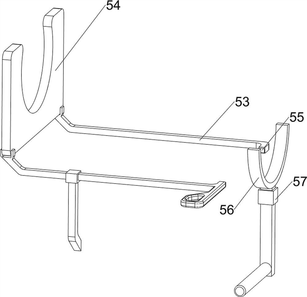
[0030] The placement assembly 2 includes a first support rod 21, a first baffle plate 22, a first placement rod 23, a first connecting rod 24, and a guide ring 25. The top left rear side of the base 1 is provided with a first support rod 21, the first support The rod 21 is provided with a first baffle 22, the first baffle 22 is provided with a first placement rod 23, the right side of the first baffle 22 is provided with a first connecting rod 24, and the first connecting rod 24 is provid...

Embodiment 2

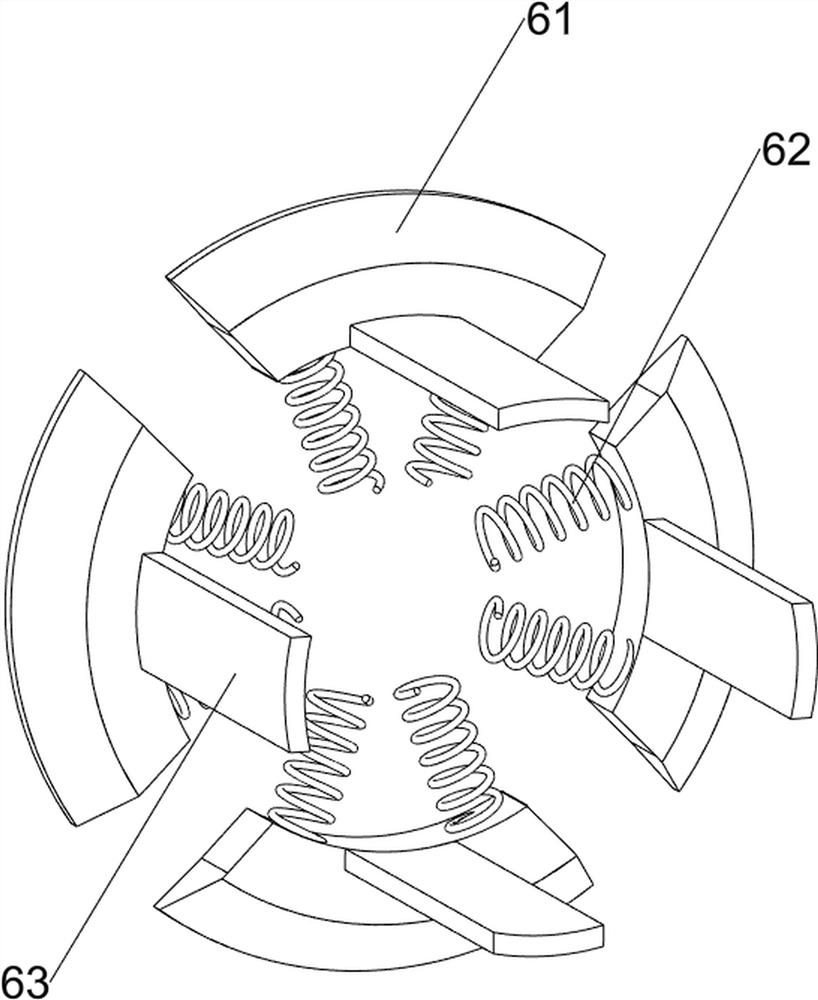
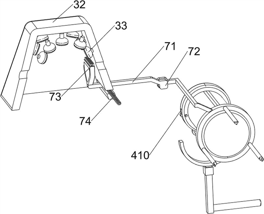
[0034] On the basis of Example 1, such as Figure 4-Figure 9 As shown, it also includes a material retrieving assembly 4, and the retrieving assembly 4 includes a third support rod 41, a servo motor 42, a second connecting rod 43, a first blocking block 44, a wedge block 45, a rotating shaft 46, a rotating rod 47, The second blocking block 48, the torsion spring 49 and the fourth support rod 410, the left and right sides of the base 1 top front side are symmetrically provided with the third support rod 41, the third support rod 41 is slidably provided with a servo motor 42, and the servo motor 42 is connected There is a second connecting rod 43, the top of the second connecting rod 43 is provided with a first stop block 44, the output shaft of the servo motor 42 is connected with a rotating shaft 46, a disc is placed on the rear side of the rotating shaft 46, and a rotating rod is arranged on the rear side of the disc 47, left and right symmetrical rotation on the disc is prov...


PUM


Abstract

The invention relates to a removal device, in particular to a dye removing device for yarn dyeing. Provided is the dye removing device for yarn dyeing aiming at achieving the technical effects that the working efficiency is improved, yarn damage is reduced, automatic cleaning is achieved, and discharged sewage is collected in a centralized mode. The technical scheme is as follows: the dye removing device for yarn dyeing comprises a base and a containing assembly, the containing assembly being arranged on one side of the base; and a cleaning assembly arranged on one side of the base. Yarn is wound on a first placing rod, a yarn head penetrates through a guide ring, the yarn penetrates through a second baffle, a spray head performing washing on the yarn, the washed yarn moves rightwards, a heating rod and a fan are used for softening and drying the yarn, sewage after cleaning is intensively discharged through a water outlet pipe, and the effects of automatic cleaning and intensively collecting and discharging the sewage are achieved.

Description

technical field [0001] The invention relates to a removing device, in particular to a dye removing device for yarn dyeing. Background technique [0002] Treatment equipment will be used in the treatment of yarn dyeing. Most of the existing treatments are carried out directly in the dyeing vat, and then the yarn in the dyeing vat is processed through a series of treatment devices, and the treated wastewater is directly discharged. It can be seen that direct discharge will waste a lot of water resources, resulting in waste of resources, and unified sewage treatment requires high treatment costs; and most of them are washed with warm water, and then Pickling is then carried out, which will result in low pickling efficiency, slow degradation, and certain damage to the yarn. [0003] In view of the problems existing in the above-mentioned prior art, it is necessary to design a dye removal device for yarn dyeing that improves work efficiency, reduces yarn damage, automatically cl...

Claims


Application Information

Patent Timeline
Patent Type & Authority Applications(China)
IPC IPC(8): D06B1/02D06B15/00D06B23/04D06B1/12
CPCD06B1/02D06B1/12D06B15/00D06B23/04
Inventor 陈力
Owner 陈笠
Why Eureka
Try Eureka