
Anti-seepage system suitable for landfill and paving method thereof

A technology of landfill and anti-seepage layer, which is applied in protection devices, buildings, infrastructure engineering, etc. It can solve the problems of pumping inclined pipes and anti-seepage system damage, so as to ensure anti-seepage performance and prevent floating and sideslip , the effect of ensuring integrity

Active Publication Date: 2021-08-03
JINAN MUNICIPAL ENG DESIGN & RES INSITITUTE GRP
View PDF4 Cites 0 Cited by
  • Summary
  • Abstract
  • Description
  • Claims
  • Application Information

AI Technical Summary

Problems solved by technology

[0004]The current anti-seepage measures for landfills are mainly to divert the seepage fluid at the bottom of the landfill by using inclined drainage pipes. The installation measures are insufficient. The scheme is directly on the anti-seepage liner system of the bottom and side walls of the reservoir, and it is easy to cause damage to the pumping and drainage inclined pipe and the anti-seepage system during landfill operations.

Method used


Image

  • Anti-seepage system suitable for landfill and paving method thereof
  • Anti-seepage system suitable for landfill and paving method thereof

Examples


Embodiment 1

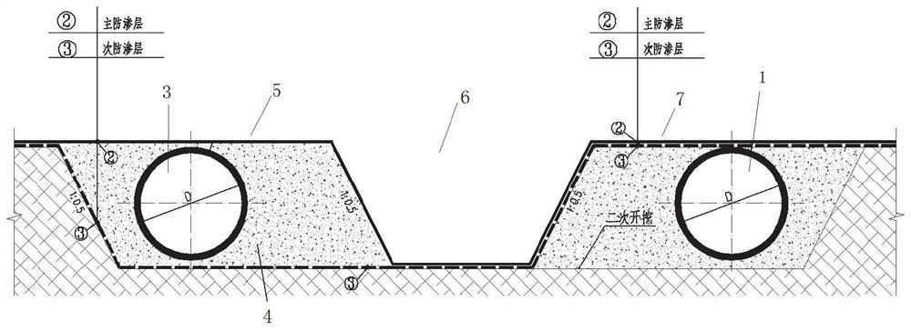
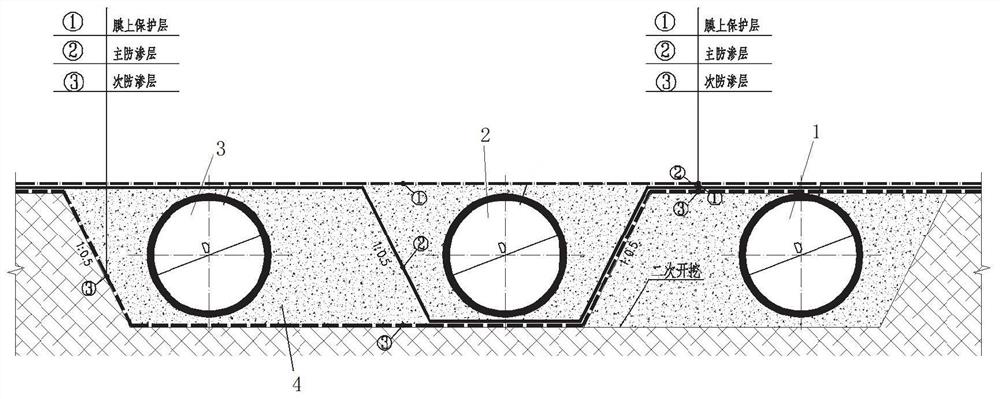
[0028] Such as Figure 1-Figure 2 As shown, the embodiment of the present disclosure provides an anti-seepage system suitable for multi-functional suction and drainage inclined pipes in landfills. The anti-seepage system mainly includes longitudinal grooves arranged on the internal slope of the landfill and arranged The groundwater pumping and discharging inclined pipe 1, the secondary leachate leak detection inclined pipe 3 and the main leachate pumping inclined pipe 2 in the longitudinal groove are described.

[0029] What needs to be explained is that the longitudinal groove is set upward along the side slope, specifically, an inverted trapezoidal groove is dug inward on the side slope.

[0030] Specifically, the three pipes, the groundwater pumping inclined pipe 1, the secondary leachate leak detection inclined pipe 3 and the main leachate pumping inclined pipe 2, are arranged in the longitudinal groove at intervals, and each pipe The surrounding area is filled with plain...

Embodiment 2

[0034] The embodiment of the present disclosure provides a pavement method for an anti-seepage system suitable for multi-functional suction and drainage inclined pipes in landfills, such as figure 1 As shown, before the method is implemented, an inverted trapezoidal groove is pre-dug on the side wall slope of the landfill. The pre-dug trapezoidal groove is pre-divided into the left area, the middle area and the right area in the internal length direction, and the main leachate pumping inclined pipe, the secondary leachate leak detection inclined pipe and the groundwater pumping inclined pipe are placed in these three areas. within an area.

[0035] Step 1: First place the inclined pipe for pumping and discharging groundwater in the right area of ​​the trapezoidal groove. During the installation process, ensure the verticality of the inclined pipe for pumping and discharging groundwater. After installing the inclined pipe for pumping and discharging groundwater, fill around the...


PUM


Abstract

The invention relates to an anti-seepage system suitable for a landfill and a paving method thereof, and belongs to the technical field of landfill construction. The anti-seepage system comprises a longitudinal groove, wherein the longitudinal groove is formed in an inner side slope of the landfill, the inner space of the longitudinal groove is divided into a first area, a second area and a third area in sequence in the length direction, an underground water pumping and draining inclined pipe is placed in the first area, a main leachate pumping and draining inclined pipe is placed in the second area, a secondary leachate leakage detecting inclined pipe is placed in the third area, the first area, the second area and the third area are filled with plain concrete, the first area, the second area and the third area are isolated from one another through impermeable layers, and an on-film protection layer is laid on the top of the groove.

Description

technical field [0001] The disclosure belongs to the technical field of landfill plant construction, and in particular relates to an anti-seepage system suitable for landfills and a paving method thereof. Background technique [0002] The statements herein merely provide background information related to the present disclosure and do not necessarily constitute prior art. [0003] The landfill anti-seepage system is an important part of the solid waste landfill. It is used to isolate the inside and outside of the landfill, prevent leachate from polluting groundwater and surface water, and prevent off-site water from entering the landfill. [0004] At present, the anti-seepage measures of landfills mainly use inclined drainage pipes to divert the seepage liquid at the bottom of the landfill, but the current installation measures for the inclined drainage pipes are insufficient, and the scheme is directly located at the bottom and side walls of the reservoir. On the anti-seepa...

Claims


Application Information

Patent Timeline
Patent Type & Authority Applications(China)
IPC IPC(8): E02D31/02E02D15/00E02D15/02
CPCE02D31/02E02D15/00E02D15/02
Inventor 高绍智甘立建刘晓红王建军许振钰尹志超
Owner JINAN MUNICIPAL ENG DESIGN & RES INSITITUTE GRP
Learn More