Heat recovery or work recovery system, ejector therefor, and fluid mixing method

A recovery system, injector technology, applied in fluid mixers, chemical instruments and methods, machines using waste heat, etc., to achieve the effect of improving efficiency

Pending Publication Date: 2021-08-03
CARRIER CORP
View PDF0 Cites 0 Cited by
  • Summary
  • Abstract
  • Description
  • Claims
  • Application Information

AI Technical Summary

Problems solved by technology

[0004] The purpose of the present invention is to solve o

Method used


Image

  • Heat recovery or work recovery system, ejector therefor, and fluid mixing method
  • Heat recovery or work recovery system, ejector therefor, and fluid mixing method
  • Heat recovery or work recovery system, ejector therefor, and fluid mixing method

Examples


Embodiment Construction

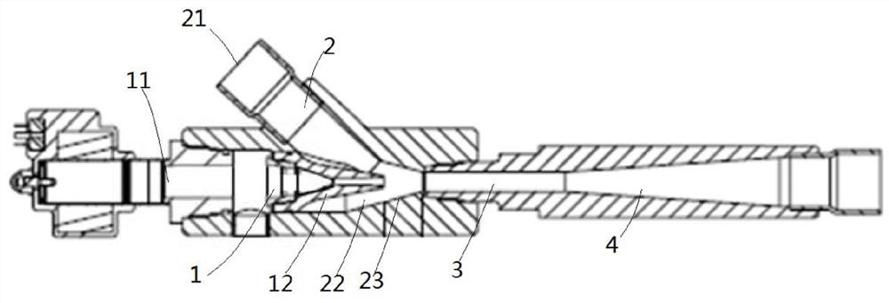
[0033] refer to figure 1 A work recovery system using an ejector according to an embodiment of the present invention will be introduced. For example, it may be a refrigeration device as an example. The work recovery system may include: a compressor 83 , the outlet of the compressor 83 is connected to the inlet of the condenser 82 downstream thereof, and the outlet of the condenser 82 is connected to the high-pressure fluid inlet 11 of the ejector 80 . On the other hand, the fluid outlet 43 of the injector 80 is connected with a separator 84 . Fluid from the fluid outlet 43 of the ejector 80 is separated in a separator with the gas phase returning to the inlet of the compressor 83 and the liquid phase passing through a valve 85 and evaporator 86 to the suction fluid inlet 21 of the ejector 80 . In the illustrated embodiment, injector 80 is used as figure 1 As shown in the work recovery system, in alternative embodiments, the injector 80 can also be applied to other types of m...


PUM

PropertyMeasurementUnit
Thicknessaaaaaaaaaa

Abstract

The invention provides an ejector for a heat recovery or work recovery system, the heat recovery or work recovery system, and a method of directing fluid therein. The ejector comprises a high-pressure fluid channel, a suction fluid channel, a mixing chamber and a diffusion chamber, wherein the high-pressure fluid channel comprises a high-pressure fluid inlet and a high-pressure fluid nozzle; the suction fluid channel comprises a suction fluid inlet and a suction chamber surrounding the high pressure fluid nozzle; the mixing chamber in fluid communication with the high-pressure fluid channel and the suction fluid channel, correspondingly; the diffusion chamber is located downstream of the mixing chamber; and the front end of the outer wall of the high-pressure fluid nozzle is provided with an arc-shaped rounding part. The ejector according to an embodiment of the present invention has improved efficiency.

Description

technical field [0001] The present invention relates to the field of heat recovery (heat recovery) or work recovery (work recovery) system, more specifically, the present invention relates to a kind of injector for heat recovery or work recovery system, heat recovery or work recovery system and heat recovery or A method of mixing fluids in a work recovery system. Background technique [0002] Commercial heat recovery or work recovery systems, especially those requiring large differential pressures, use ejectors to improve efficiency. The ejector pressurizes the suction fluid, for example with high pressure fluid, and provides the mixed fluid to the compressor inlet, thereby increasing the pressure of the compressor inlet fluid, thereby reducing the demand on compressor capacity and increasing the efficiency of the system. [0003] Ejectors usually include high-pressure fluid nozzles to convert high-pressure fluid into high-momentum fluid. The suction fluid is sucked along w...

Claims


Application Information

Patent Timeline
IPC IPC(8): F25B9/08F25B27/02B05D1/02B05B7/04
CPCF25B9/08F25B27/02B05D1/02B05B7/0408F04F5/463F25B2400/23F25B41/00F25B2341/0012F04F5/24B01F25/31243
Inventor 张薇P.韦尔马
Owner CARRIER CORP
Why Eureka
Try Eureka