Diameter detection method and device suitable for cast pipe production line

A detection device and detection method technology, applied in the direction of measuring devices, optical devices, instruments, etc., can solve the problems of large diameter cast pipe curvature changes, poor detection accuracy, high cost, etc., to achieve large cast pipe range, structure Simple, easy-to-maintain effects

Pending Publication Date: 2021-08-03
XINXING HEBEI ENG & RES INC
View PDF1 Cites 0 Cited by
  • Summary
  • Abstract
  • Description
  • Claims
  • Application Information

AI Technical Summary

Problems solved by technology

The disadvantages of this method are mainly: ①. The detection accuracy is poor. When the diameters of cast pipes are adjacent, wrong comparison results are often obtained; (such as adjusting the spacing of supporting wheels, etc.), all the parameters set need to be re-input; ③, when the casting tube rotates, the casting tube to be tested may jump up and down, and the accuracy cannot be guaranteed by unilateral laser detection; 2. Use the up and down The disadvantages of this method are: ①, the laser sensor is installed from bottom to top, the lens is easy to get dirty, and the maintenance is cumbersome; ②, due to the small space at the lower end of the cast pipe, a high-precision and small-range laser must be used, and the cost High; 3. According to a device disclosed by the patent CN104359413A that uses a laser displacement sensor to measure the diameter of a steel pipe, multiple sets of laser detection and calculations are used, but the disadvantage of this method is that it is difficult for the device to detect large diameter cast pipes due to large curvature changes. Diameter cast pipe

Method used


Image

  • Diameter detection method and device suitable for cast pipe production line
  • Diameter detection method and device suitable for cast pipe production line
  • Diameter detection method and device suitable for cast pipe production line

Examples


Embodiment Construction

[0021] The following will clearly and completely describe the technical solutions in the embodiments of the present invention with reference to the accompanying drawings in the embodiments of the present invention. Obviously, the described embodiments are only some, not all, embodiments of the present invention.

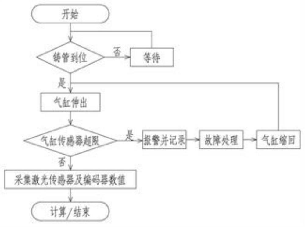
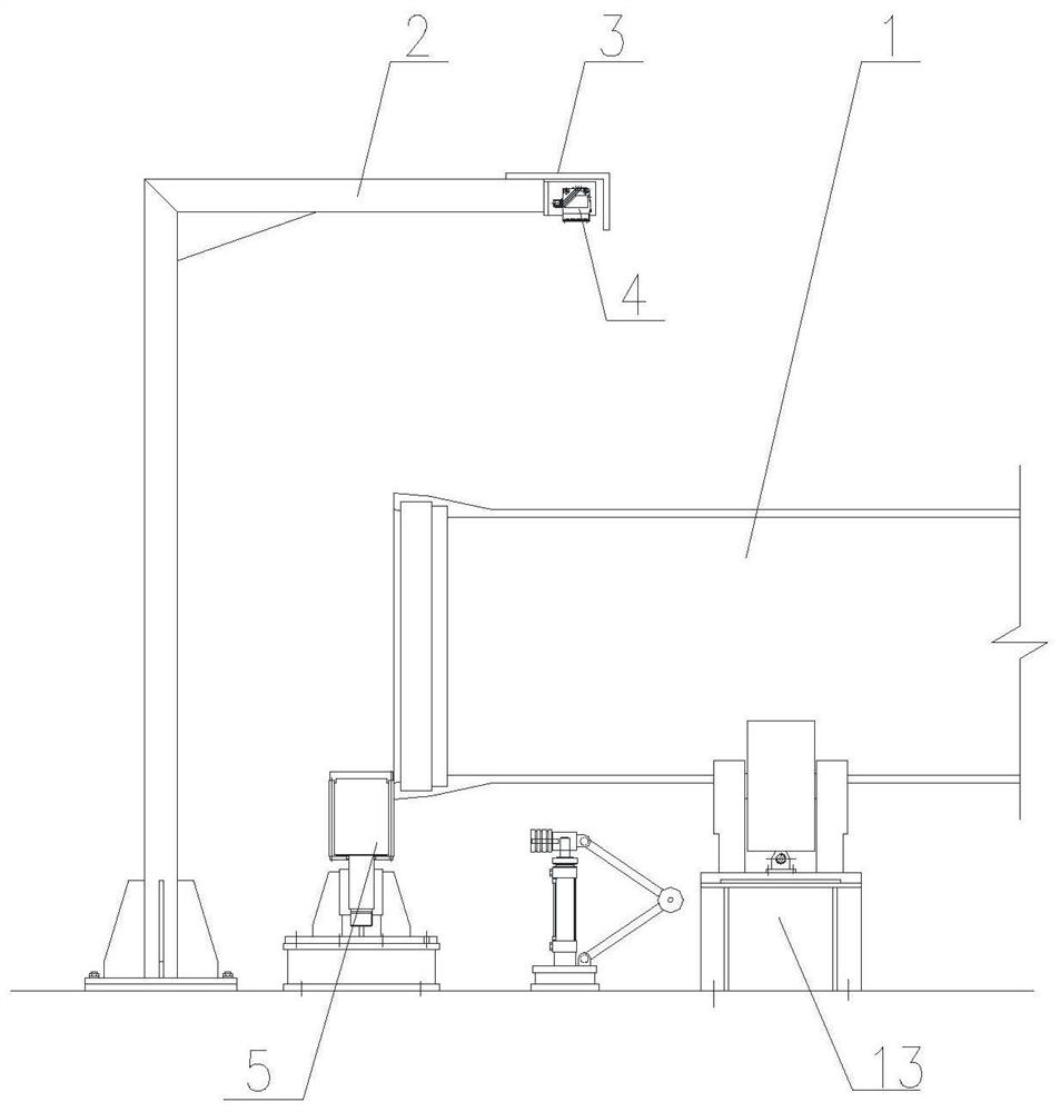
[0022] Such as figure 1 , 4 Shown, a kind of diameter detecting method that is suitable for cast pipe production line, comprises the following steps: A, measure the height L of the lower plane of laser sensor 4 to the ground 1 , L 1 Stored in the PLC controller as known data;

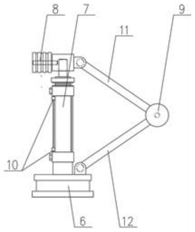
[0023] B. Measure the height L of the magnetic cylinder 7 contacting the roller 8 to the ground of the lower section detection device of the cast pipe when it is not extended 2 , L 2 Stored in the PLC controller as known data;

[0024] C. Calculate L 3 = L 1 -L 2 , stored in the PLC controller;

[0025] D. When the casting pipe 1 is sent from the previous station to the supporting rol...


PUM


Abstract

The invention provides a diameter detection method suitable for a cast pipe production line. The diameter detection method comprises the following steps of: A, measuring the height L1 from the lower plane of a laser sensor to the ground; B, measuring the height L2 of the contact roller to the ground when the magnetic cylinder does not extend out; C, calculating L3=L1-L2, and storing the L3 into a PLC (Programmable Logic Controller); D, after the laser sensor detects the cast pipe, judging that the pipe exists; e, reading the numerical value of the laser sensor, and obtaining the height Lu1 from the laser sensor to the upper tangent plane of the cast pipe; and F, reading the numerical value of the encoder, obtaining the extension length Ld1 of the magnetic air cylinder, and at the moment, the diameter Lx1 of the cast pipe is obtained and is equal to L3-Lu1-Ld1. The device is simple in structure, convenient to disassemble and assemble and easy to maintain; the upper and lower horizontal sections of the cast pipe body can be simultaneously detected, and when the position of the cast pipe changes up and down or rotates and jumps, the detection precision is not influenced; and the device is large in detectable cast pipe range, and is suitable for diameter detection of cast pipes or steel pipes of all specifications at present.

Description

technical field [0001] The invention belongs to the technical field of cast pipe production, and in particular relates to a diameter detection method and device suitable for a cast pipe production line. Background technique [0002] At present, in the cast pipe production process, stable and rapid detection of the cast pipe diameter is a prerequisite for realizing the automatic operation of the cast pipe production line. With the improvement of equipment level, the cast pipe production line basically realizes automatic operation, but in the actual production process, the pipe diameter parameters often become the "bottleneck" of automatic operation of equipment. In the current production lines, the main methods for detecting the diameter of the cast pipe are: 1. Use a single laser to irradiate the highest point of the cast pipe body from top to bottom, and then compare the feedback value with the known pipe diameter feedback value to obtain the Measure the pipe diameter. Th...

Claims


Application Information

Patent Timeline
IPC IPC(8): G01B11/08
CPCG01B11/08
Inventor 张济凡刘路召胡桥木杨娜周伟王军舰王腾超
Owner XINXING HEBEI ENG & RES INC
Why Eureka
Try Eureka