Eureka AIR delivers breakthrough ideas for toughest innovation challenges, trusted by R&D personnel around the world.

Receiver pulse signal interference evaluation method based on error rate

A pulse signal and receiver technology, applied in receiver monitoring, transmission monitoring, electrical components, etc., can solve the difference between pulse signal interference and noise interference, complex and variable pulse signal parameters and modulation methods that have not been studied in depth and other issues, to achieve an objective, fast, and highly credible evaluation process

Active Publication Date: 2021-08-03
BEIHANG UNIV
View PDF5 Cites 2 Cited by
  • Summary
  • Abstract
  • Description
  • Claims
  • Application Information

AI Technical Summary

Problems solved by technology

[0006] 1) Existing research draws on the traditional method of noise interference, and uses statistical laws to deal with the problem of pulse signal interference, without distinguishing the difference between pulse signal interference and noise interference, and some pulse interference phenomena in experimental tests cannot be explained by existing theories;
[0007] 2) Based on the evaluation of the interference degree of the receiver based on the pulse signal power and the interference link model, there is no in-depth research on the complex and variable pulse signal parameters and modulation methods

Method used


Image

  • Receiver pulse signal interference evaluation method based on error rate
  • Receiver pulse signal interference evaluation method based on error rate
  • Receiver pulse signal interference evaluation method based on error rate

Examples


Embodiment Construction

[0053] The technical solution of the present invention will be further described in detail below in conjunction with the accompanying drawings, but the protection scope of the present invention is not limited to the following description.

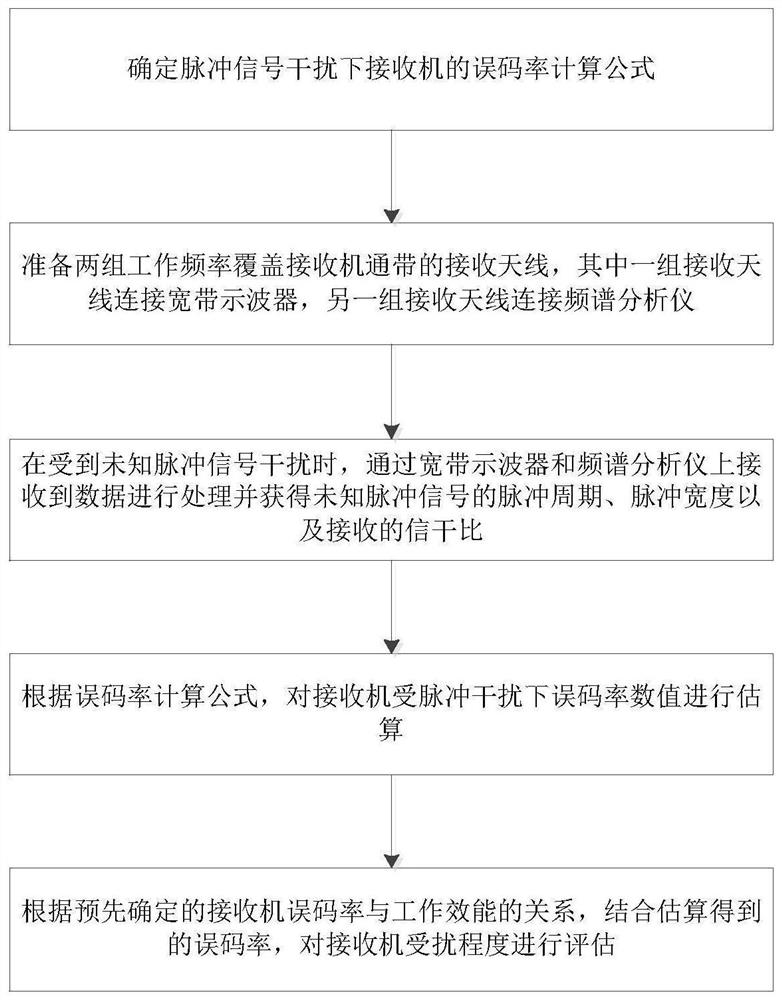
[0054] Such as figure 1 As shown, a method for evaluating receiver pulse signal interference based on bit error rate includes the following steps:

[0055] S1. Determine the formula for calculating the bit error rate of the receiver under pulse signal interference;

[0056] Such as figure 2Shown is a typical receiver - superheterodyne receiver basic composition block diagram. The block diagram is mainly composed of three parts: receiving antenna, frequency mixing circuit and demodulation circuit. The useful signal enters the receiver through the receiving antenna and band-pass filter, moves to the intermediate frequency part (usually a fixed value) after being mixed, and then moves to the base frequency through down-conversion, and can ...


PUM


Abstract

The invention discloses a receiver pulse signal interference evaluation method based on an error rate. The method comprises the following steps: S1, determining an error rate calculation formula of a receiver under pulse signal interference; s2, preparing two groups of receiving antennas of which the working frequencies cover the passband of the receiver, wherein one group of receiving antennas is connected with a broadband oscilloscope, and the other group of receiving antennas is connected with a spectrum analyzer; s3, processing the data received by the broadband oscilloscope and the spectrum analyzer and obtaining the pulse period, the pulse width and the received signal to interference ratio of the unknown pulse signal when being interfered by the unknown pulse signal; s4, estimating the bit error rate value of the receiver under the pulse interference according to the bit error rate calculation formula obtained in the step S1; and S5, evaluating the disturbed degree of the receiver according to the predetermined relationship between the bit error rate and the working efficiency of the receiver and the estimated error rate. According to the method, the interference degree of the pulse signal on the receiver is objectively quantified, and the effectiveness of the evaluation result is ensured.

Description

technical field [0001] The invention relates to receiver interference evaluation, in particular to a receiver pulse signal interference evaluation method based on bit error rate. Background technique [0002] Communication technology is widely used in various fields of modern science and technology. Since entering the 21st century, it has played an important role in perception and command in various scenarios, and is also the most vulnerable to interference from the electromagnetic environment. Research at home and abroad mainly focuses on the mutual interference between pulse signal systems, such as the electromagnetic compatibility problem between radar systems, but there are relatively few studies on pulse signal interference communication systems. [0003] Receiver sensitivity defines the minimum signal strength that the receiver can receive and still work normally. In order to maintain the minimum acceptable signal strength of the receiver to work normally, the sensitiv...

Claims


Application Information

Patent Timeline
Patent Type & Authority Applications(China)
IPC IPC(8): H04B17/20H04B17/336H04B17/345
CPCH04B17/20H04B17/336H04B17/345
Inventor 李尧尧朱恒蔡少雄胡蓉苏东林
Owner BEIHANG UNIV
Why Eureka
Eureka Blog
Learn More