Cutting device for die part production

A cutting device and parts technology, which is applied in the field of cutting devices for mold parts production, can solve the problems of inability to change, loose fixation, and inability to cut the cutting position of circular parts, etc., and achieve the effect of easy adjustment

Active Publication Date: 2021-08-06
南通维益机电有限公司
View PDF10 Cites 3 Cited by
  • Summary
  • Abstract
  • Description
  • Claims
  • Application Information

AI Technical Summary

Problems solved by technology

[0009] The purpose of the present invention is to solve the problems in the prior art that the fixation is not firm, the circular parts cannot be cut and the cutting position cannot be changed, and a cutting device for the production of mold parts is proposed.

Method used


Image

  • Cutting device for die part production
  • Cutting device for die part production
  • Cutting device for die part production

Examples


Embodiment Construction

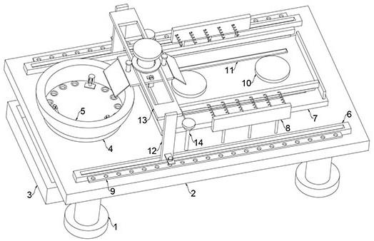
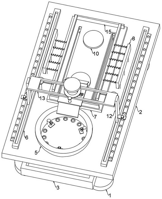
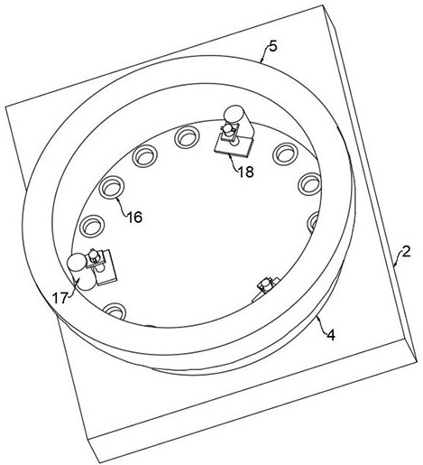
[0046] refer to Figure 1-4 , a cutting device for mold parts production, comprising an operating platform 2 fixedly installed on a plurality of support columns 1, a disc 4 and a fixed plate 7 are fixedly installed on the operating platform 2, and a plurality of fixed rods 17 pass through the disc 4 A plurality of straight plates 20 are fixedly installed, and each straight plate 20 is equipped with a pressing plate 18 through a pressing mechanism;

[0047] There are two points worth noting above:

[0048] 1. A straight plate 20 is fixedly installed on the fixed rod 17. A threaded rod 19 is threaded on the straight plate 20. The lower end of the threaded rod 19 is fixedly mounted with a limit shaft, and the pressing plate 18 is rotated and installed on the limit shaft. The pressing plate 18 and the straight plate Two limit springs are fixedly installed between 20, and the round part is placed in the disc 4, and the threaded rod 19 is rotated to drive the pressing plate 18 to d...


PUM


Abstract

The invention discloses a cutting device for die part production. The cutting device comprises an operating platform fixedly mounted on a plurality of supporting columns, a disc and a fixing plate are fixedly mounted on the operating platform, a plurality of straight plates are fixedly mounted on the disc through a plurality of fixing rods, a pressing plate is mounted on each straight plate through a pressing mechanism, two side plates are fixedly installed on the operating platform through a plurality of vertical rods, a collecting mechanism is jointly installed among the fixing plate, the disc, the two side plates and the operating platform, and a cutting assembly is installed on the operating platform. The cutting device has the advantages that strip-shaped, square or circular parts can be cut, the cutting range is wide, the parts can be firmly and stably fixed, the parts cannot shake during cutting, the cutting angle, length and position can be flexibly adjusted, and the cutting efficiency is high.

Description

technical field [0001] The invention relates to the technical field of mold parts, in particular to a cutting device for the production of mold parts. Background technique [0002] Mold refers to a mold and tool composed of multiple parts. It is mainly used for molding products in injection molding, blow molding, forging and other processes. After the mold parts are produced, they usually need to be cut with a cutting device to In order to get the appropriate mold size and shape; [0003] After searching, the Chinese authorized invention patent with the patent number CN212599430U discloses a cutting device for the production of hardware parts, including a load-bearing plate and a filter device fixed on one side of the bottom end of the load-bearing plate, and the four corners of the bottom end of the load-bearing plate are all fixedly welded There are supporting legs, and there are multiple sets of chute symmetrically arranged on both sides of the top of the load-bearing pl...

Claims


Application Information

Patent Timeline
Patent Type & Authority Applications(China)
IPC IPC(8): B23D19/00B23D33/02B23Q1/62B23Q11/00
CPCB23D19/00B23D33/02B23Q1/621B23Q11/0067
Inventor 姜小波
Owner 南通维益机电有限公司
Why Eureka
Try Eureka