
Electromechanical cutting auxiliary equipment with automatic speed fixing function

A technology of auxiliary equipment and constant speed, applied in metal processing equipment, positioning devices, manufacturing tools, etc., can solve problems such as flying knives, damage to mechanical parts, injury to people, etc., to improve safety performance, improve purification, The effect of preventing flying knives

Inactive Publication Date: 2021-08-06
东莞市社利机电科技有限公司
View PDF0 Cites 0 Cited by
  • Summary
  • Abstract
  • Description
  • Claims
  • Application Information

AI Technical Summary

Problems solved by technology

[0003] However, in the electromechanical cutting machine equipment, when cutting, the cutting head is often broken due to the speed is too fast or the processing task cannot be completed due to the slow speed. Sometimes it is easy to cause damage to other mechanical parts, and even hurt people seriously. The safety performance is relatively low, which is not conducive to people's safe production. Not only that, the iron filings exposed on both sides of the cutting machine can easily make the environment inside the electromechanical equipment messy. The environment is not clean enough, which is not conducive to energy saving and environmental protection. Therefore, an electromechanical cutting auxiliary equipment with automatic constant speed function came into being.

Method used


Image

  • Electromechanical cutting auxiliary equipment with automatic speed fixing function
  • Electromechanical cutting auxiliary equipment with automatic speed fixing function
  • Electromechanical cutting auxiliary equipment with automatic speed fixing function

Examples


Embodiment Construction

[0025] The following will clearly and completely describe the technical solutions in the embodiments of the present invention with reference to the accompanying drawings in the embodiments of the present invention. Obviously, the described embodiments are only some, not all, embodiments of the present invention. Based on the embodiments of the present invention, all other embodiments obtained by persons of ordinary skill in the art without making creative efforts belong to the protection scope of the present invention.

[0026] see Figure 1-5 :

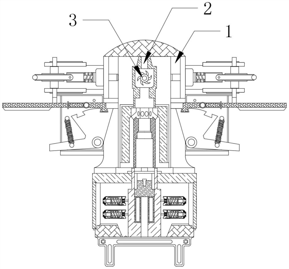
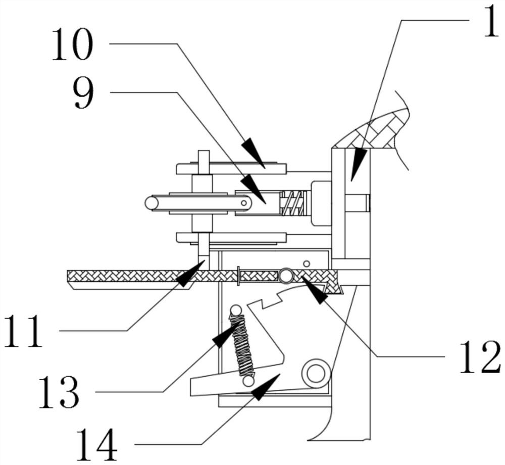
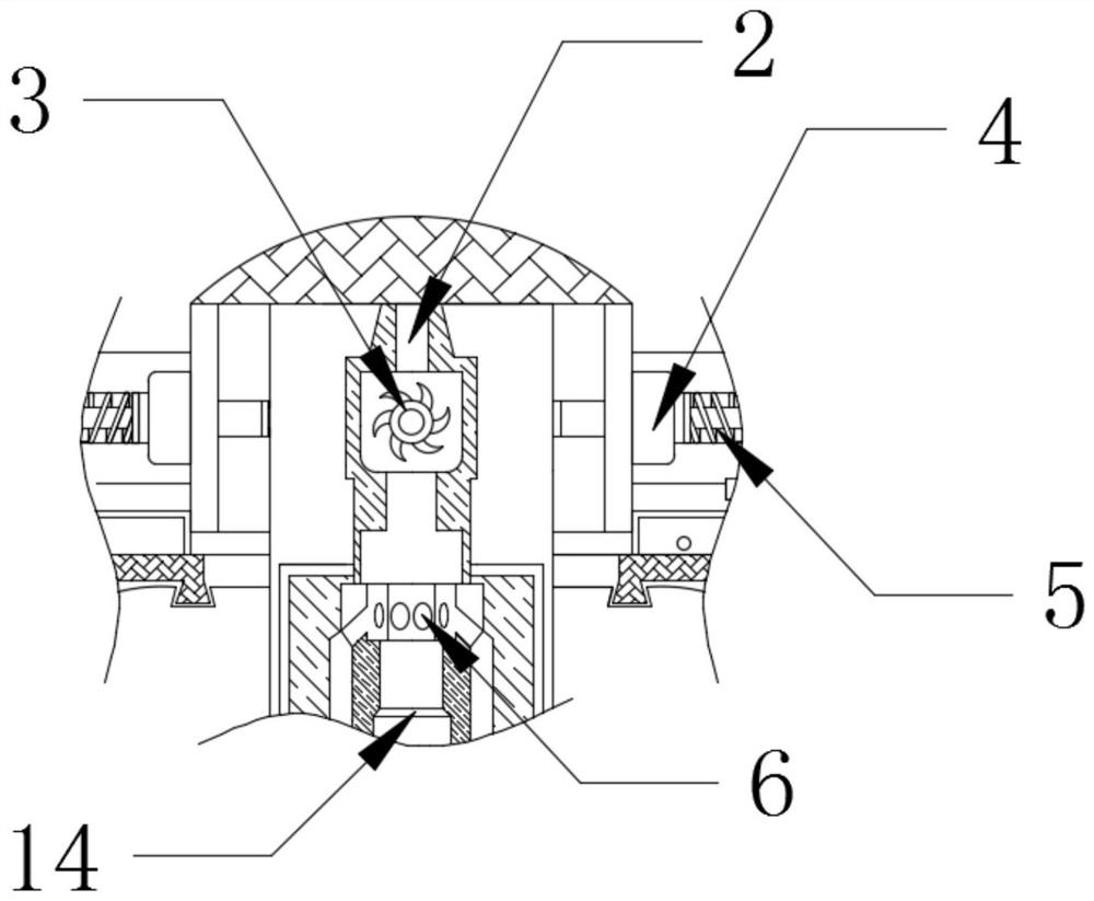
[0027] An electromechanical cutting auxiliary device with an automatic constant speed function, comprising a main body 1, a round rod 2 is movably connected to the top of the main body 1 above the rotating fan 3, and a rotating fan 3 is movably connected to the lower end of the round rod 2 and located in the middle of the core lock block 12 , this structure has stability and ease of use; the top of the main body 1 is movably connect...


PUM


Abstract

The invention relates to the technical field of electromechanical equipment, and discloses electromechanical cutting auxiliary equipment with an automatic speed fixing function. Protection parts are movably mounted on the left side and the right side of a rotating fan. According to the electromechanical cutting auxiliary equipment with the automatic speed fixing function, a round rod extrudes the axis of the rotating fan to a certain extent, the rotating fan rotates anticlockwise under the action of extrusion force, the round rod pushes the protection parts to operate when moving downwards, a mounting block moves in the direction away from the round rod in the horizontal direction, a pull rod releases a rotating disc to move anticlockwise, when the rotating speed of the rotating disc is smaller than that of a core locking block, the core locking block is inserted into the rotating disc, the rotating speed of the rotating disc is locked under the action of the core locking block, so that normal operation of equipment is guaranteed, the production quality of electromechanical equipment is optimal, the fly-cutter condition is prevented, the safety performance is improved, and the production is promoted.

Description

technical field [0001] The invention relates to the technical field of electromechanical equipment, in particular to an electromechanical cutting auxiliary equipment with an automatic speed-fixing function. Background technique [0002] With the continuous improvement of technology, traditional mechanical equipment has entered a new stage of the combination of mechanical and electrical, and its application scope has been continuously expanded. Mechanical and electrical equipment generally refers to machinery, electrical appliances and electrical automation equipment. In construction, it mostly refers to geotechnical, carpentry, The general term for machinery and pipeline equipment other than steel bars and muddy water generally meets the standards of intelligent manufacturing. It is different from hardware and refers to finished products that can achieve certain functions. [0003] However, in the electromechanical cutting machine equipment, when cutting, the cutting head is...

Claims


Application Information

Patent Timeline
IPC IPC(8): B23Q11/12B23Q11/00B23Q3/00B01D50/00
CPCB23Q11/12B23Q11/005B23Q3/00B01D50/60
Inventor 刘权
Owner 东莞市社利机电科技有限公司
Learn More