
Temporary connection structure between truss type steel pipe framework sections and arch bridge

A steel tube skeleton and temporary connection technology, applied in arch bridges, erecting/assembling bridges, bridges, etc., can solve problems such as increasing operating procedures, affecting construction period, quality defects, etc., reducing the number of bolts, reducing engineering costs, and large safety margins Effect

Pending Publication Date: 2021-08-06
SICHUAN DEPT OF TRANSPORTATION HIGHWAY PLANNING PROSPECTING & DESIGN RES INST
View PDF25 Cites 0 Cited by
  • Summary
  • Abstract
  • Description
  • Claims
  • Application Information

AI Technical Summary

Problems solved by technology

The high-strength bolt connection is designed according to equal strength, and the number of bolts required for each connecting plate is large, which is limited by the minimum distance between the bolt center and the minimum distance to the edge, resulting in a large size of the high-strength bolt connection structure. Grinding it off beforehand will not only increase the operating procedures and affect the construction period, but also the secondary processing on the stressed structure will easily cause quality defects, and the construction is very difficult

Method used


Image

  • Temporary connection structure between truss type steel pipe framework sections and arch bridge
  • Temporary connection structure between truss type steel pipe framework sections and arch bridge
  • Temporary connection structure between truss type steel pipe framework sections and arch bridge

Examples


Embodiment 1

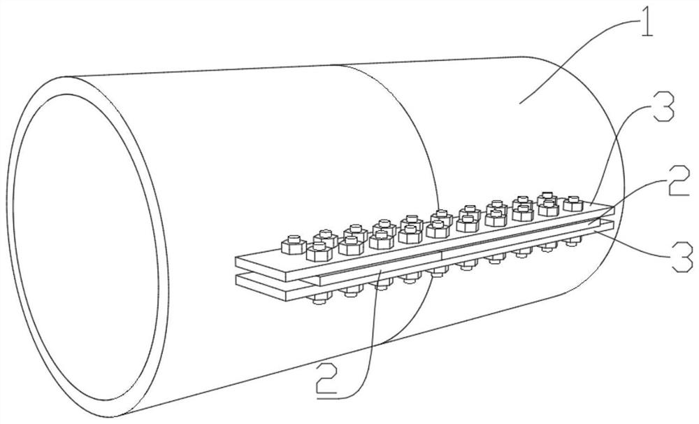
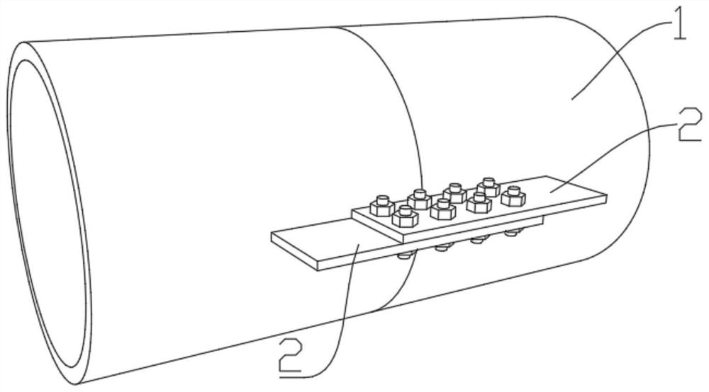
[0041] A temporary connection structure between truss-type steel pipe skeleton segments described in this embodiment is used to temporarily connect two axially adjacent skeleton main pipes 1, and the outer wall of the end of the skeleton main pipe 1 is provided with at least two A connection assembly, the connection assembly is evenly spaced along the circumference of the framework main pipe 1, and the connection assembly includes at least one connecting ear plate 2 arranged axially along the skeleton main pipe 1, two of the skeleton main pipes 1 The corresponding two connecting ear plates 2 are bolted. The number of the connecting components can be adjusted accordingly according to the force requirements of the actual structure, such as two, four, etc., but there should be at least two connecting components, and the number of connecting lugs 2 included in each connecting component is based on the design The needs are determined.

[0042] The bolts are ordinary bolts, the num...

Embodiment 2

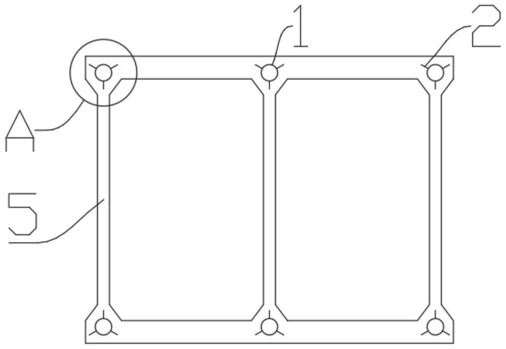
[0047] The temporary connection structure between the segments of a truss-type steel pipe skeleton described in this embodiment is roughly the same in structure as in Embodiment 1, the difference is that, as Figure 3-4 As shown, the outer wall of the end part of the framework main pipe 1 described in this embodiment is provided with three connecting assemblies, and the angle between two adjacent connecting assemblies is 120°. Of course, it is allowed to exist within ±5° Processing and installation errors, one of the connecting components points to the web 5 of the outsourcing concrete, that is, the height direction of the connecting component points to the middle of the thickness direction of the web 5, which is beneficial to the other two connecting components towards the outer concrete. The thick position, that is, the effective space corresponding to the outsourcing concrete section, can avoid secondary processing on the stressed structure beyond the connection structure of...

Embodiment 3

[0050] On the basis of Embodiment 1 or Embodiment 2, further, two guide plates 4 are connected to the inner side wall of one of the ends of the two butted skeleton main pipes 1, of course, three or four guide plates 4 can also be provided, Properly set according to the pipe diameter of the skeleton main pipe 1, the guide plate 4 is used to guide two skeleton main pipes 1 to dock when working at heights. If the guide plate 4 is a chamfered trapezoidal steel plate, the connection between the guide plate 4 and the inner side wall of the framework main pipe 1 can be single-sided fillet weld. The setting of described guide plate 4 sees Figure 6-7 , Image 6 The end face of the connecting ear plate 2 is aligned with the end face of the skeleton main pipe 1, Figure 7 The end face of the connecting ear plate 2 and the end face of the skeleton main pipe 1 are misplaced, and can be connected through the assembly plate 3 Image 6 not shown.


PUM


Abstract

The invention relates to the technical field of bridge engineering construction, in particular to a temporary connection structure between truss type steel pipe framework sections and an arch bridge. The temporary connecting structure is used for connecting two axially adjacent framework main pipes, at least two connecting assemblies are arranged on the outer side walls of the ends of the framework main pipes, the connecting assemblies are evenly distributed in the circumferential direction of the framework main pipes at intervals, and each connecting assembly comprises at least one connecting lug plate arranged in the axial direction of the framework main pipes. The two connecting lug plates corresponding to the two framework main pipes are connected through bolts. The technical prejudice in the prior art is overcome, the common bolts are adopted, the installation procedure of the common bolt group is simple, the high-altitude installation time is short, and safety and rapidness are achieved. And the size of the connecting structure adopting the common bolt is smaller, and the height of the connecting structure does not exceed the thickness of the encased concrete, so that the temporary connecting structure does not need to be cut off in the subsequent encased concrete process, the quality defect caused by secondary processing on the stress structure is avoided, and the construction difficulty and risk are reduced.

Description

technical field [0001] The invention relates to the technical field of bridge engineering construction, and is used for a reinforced concrete arch bridge constructed by a steel pipe concrete stiff skeleton construction method, in particular to a temporary connection structure between truss steel pipe skeleton segments and an arch bridge. Background technique [0002] The concrete-filled steel tube stiff skeleton method is more commonly used in the construction of reinforced concrete arch bridges. It refers to the construction method of using strong truss-type concrete-filled steel tubes as the skeleton and outsourcing the reinforced concrete to form the arch. The steel tube concrete stiff skeleton is composed of truss-type empty steel pipe skeleton segments to form an arch, and then concrete is poured into the main pipe of the skeleton. When multiple truss-type empty steel pipe skeleton sections are installed section by section, the skeleton main pipes of the truss-type holl...

Claims


Application Information

Patent Timeline
Patent Type & Authority Applications(China)
IPC IPC(8): E01D21/00E01D19/00E01D4/00E01D101/26
CPCE01D21/00E01D19/00E01D4/00E01D2101/268
Inventor 牟廷敏康玲范碧琨梁健赵艺程李畅李成君肖雨孙才志许诺柏颢原
Owner SICHUAN DEPT OF TRANSPORTATION HIGHWAY PLANNING PROSPECTING & DESIGN RES INST
Learn More