Intelligent optical fiber junction box

An intelligent optical fiber and junction box technology, which is applied to optics, light guides, optical components, etc., can solve the problems of inconvenient optical fiber coiling and fixing, and achieve the effects of reducing transmission loss, simplifying coiling operations, and high thermal conductivity.

Active Publication Date: 2021-08-06
ZG TECH SHENZHEN
View PDF9 Cites 1 Cited by
  • Summary
  • Abstract
  • Description
  • Claims
  • Application Information

AI Technical Summary

Problems solved by technology

[0005] In view of the above-mentioned related technologies, the inventor believes that due to the resilience of the bent optical fiber, there is a defect that it is not convenient to coil and fix the optical fiber

Method used


Image

  • Intelligent optical fiber junction box
  • Intelligent optical fiber junction box
  • Intelligent optical fiber junction box

Examples


Embodiment 1

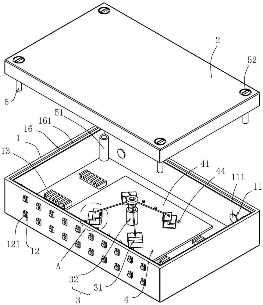
[0041] refer to figure 1 , The intelligent optical fiber junction box includes a box body 1 , a box cover 2 , a winding mechanism 3 , a cooling mechanism 4 and a fixing mechanism 5 . The cooling mechanism 4 and the winding mechanism 3 are arranged on the box body 1, the box cover 2 is set on the box body 1 through the fixing mechanism 5, and two wire inlet holes 11 are provided on the side wall of the box body 1, and the wire inlet holes 11 The middle plug is provided with a plug 111, and a plurality of outlet holes 12 are opened on the other side wall, and an optical fiber fixing seat 121 is clamped in the outlet hole 12, and the bottom wall of the box body 1 is also bonded for clamping the optical fiber fusion splicing section The card socket 13.

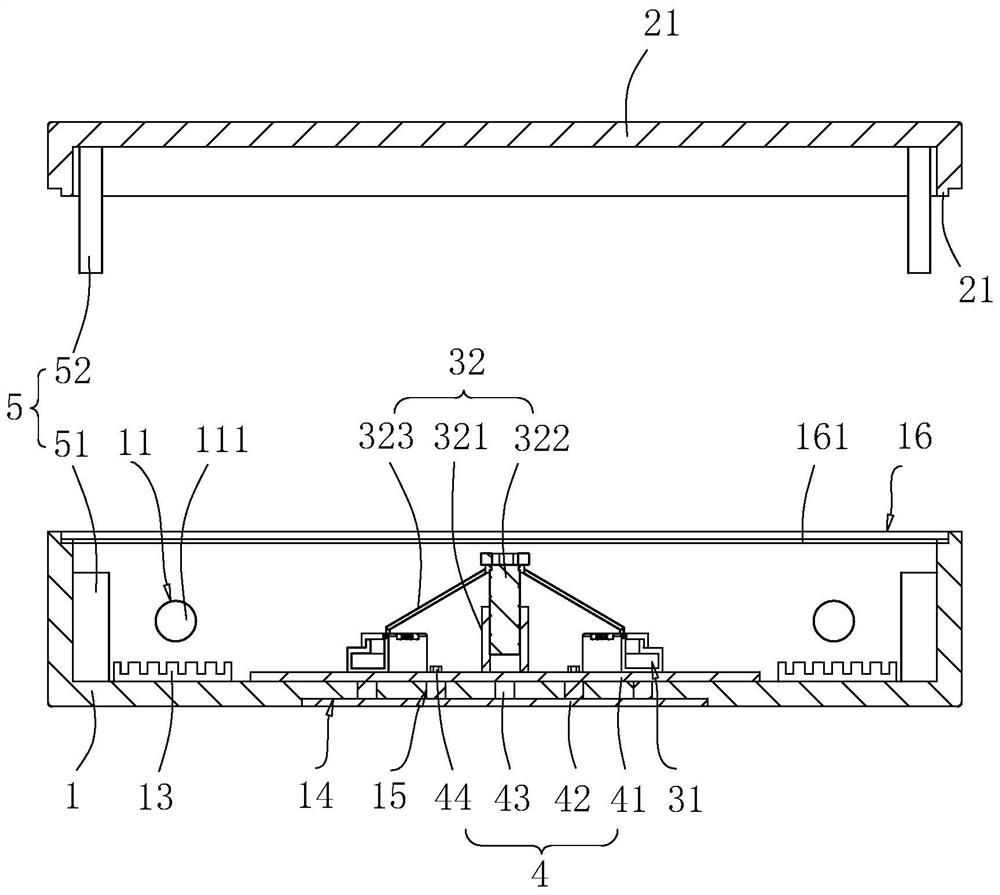
[0042] refer to figure 2 The cooling mechanism 4 includes a first heat conduction plate 41, a second heat conduction plate 42, and a plurality of heat conduction fins 43. In this embodiment, the first heat conduction plate 41, ...

Embodiment 2

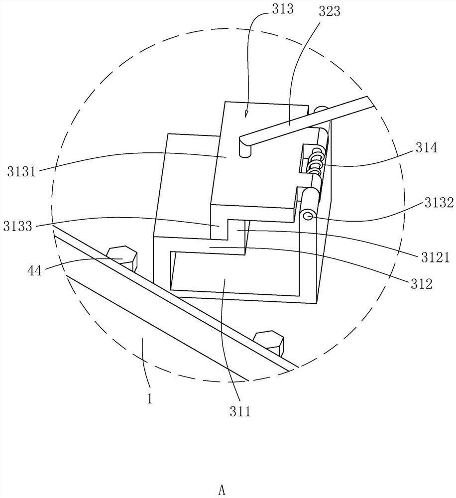
[0049] refer to Figure 5 , the difference between this embodiment and embodiment 1 is: refer to Figure 4 and Figure 5 , the movable part 313 includes a fixed plate 3134, a square bar 3135 and a third clamping vertical plate 3136, the fixed plate 3134 is welded on the top wall of the buckle 311 away from the side of the baffle plate 312, the fixed plate 3134 is higher than the first clamp The connecting riser 3121 is provided, and the height difference between the fixing plate 3134 and the first engaging riser 3121 is also larger than the fiber diameter. In this embodiment, the height difference between the fixing plate 3134 and the first engaging riser 3121 is set to 10mm. The square rod 3135 runs through the fixed plate 3134 in the radial direction along the corresponding point of the circumscribed circle of the clamping assembly 31 and is slidably connected with the fixed plate 3134. The third clamping vertical plate 3136 is welded on the side wall of the square rod 3135...


PUM

PropertyMeasurementUnit
Radiusaaaaaaaaaa
Radiusaaaaaaaaaa

Abstract

The invention relates to an intelligent optical fiber junction box, in particular to the field of optical fiber connecting devices, the intelligent optical fiber junction box comprises a box body and a box cover, the box cover covers the box body, a wire inlet hole and a wire outlet hole are formed in the box body, a wire coiling mechanism is arranged in the box body, the wire coiling mechanism comprises at least three clamping assemblies, and the radius of the circumcircle of each clamping assembly is not smaller than 30 mm; the clamping assembly comprises a clamping buckle, an opening blocking plate, a movable piece and an elastic piece, a clamping through groove is formed in the top of the clamping buckle, the opening blocking plate is fixedly arranged on the side, close to the side wall of the box body, of an opening of the clamping through groove, and the minimum distance between the opening blocking plate and the groove wall, away from the side wall of the box body, of the clamping through groove is larger than the diameter of an optical fiber, the movable piece is movably connected to the side, away from the side wall of the box body, of the opening of the clamping through groove, the elastic piece is arranged between the movable piece and the clamping buckle and enables the movable piece to tend to abut against the opening blocking plate, and when the movable piece abuts against the opening blocking plate, the opening blocking plate and the movable piece jointly seal the opening of the clamping through groove. The optical fiber coiling device has the effect of conveniently coiling and fixing the optical fiber.

Description

technical field [0001] The present application relates to the field of optical fiber connection devices, in particular to an intelligent optical fiber junction box. Background technique [0002] Optical fiber is the abbreviation of optical fiber. Nowadays, optical fiber has become the main transmission mode in the world communication because of its transmission frequency bandwidth, high anti-interference and low signal attenuation, which are far superior to cables and microwave communication transmission. In engineering construction, in order to facilitate the installation of subsequent optical fibers and to facilitate the distribution of optical cables, the optical fiber junction box is used to distribute the main optical cable to each sub-optical fiber for use. [0003] The Chinese invention patent with the application number 201811394095.4 discloses a dustproof and rainproof outdoor optical fiber junction box, including a box body, one end of the box body is connected wi...

Claims


Application Information

Patent Timeline
IPC IPC(8): G02B6/44
CPCG02B6/4446
Inventor 林友生谢运刚孙友华杨娥胡娟
Owner ZG TECH SHENZHEN
Why Eureka
Try Eureka