Excavator handle control system for remote operation

A handle control and remote operation technology, which is applied in the field of remote control driving, can solve the problems of the decrease in the accuracy and smoothness of handle manipulation, insufficient interference suppression ability and stability, and reduced service life of the handle, so as to improve the sense of presence and good remote control. The effect of control and the effect of improving the service life

Active Publication Date: 2021-08-06
GUANGZHOU INST OF ADVANCED TECH CHINESE ACAD OF SCI
6 Cites 0 Cited by

AI-Extracted Technical Summary

Problems solved by technology

[0006] The current remote control operating handle uses a sliding potentiometer to detect the action position of the handle, but because it uses a contact sensor, it is easy to cause mechanical wear under high-frequency ...

Method used

A kind of excavator handle control system for remote operation provided by the embodiment of the present invention adopts the handle control method based on Hall sensor to realize non-contact rocker data sensing, and reduce the impact caused by contact and movement wear. The influence of the service life of the handle has the characteristics of high sensitivity and good performance, which makes the operation of the handle mechanism more flexible and improves the service life of the handle; adopts the method of cooperative control of both hands, and uses two three-degree-of-freedom handles to simulate the real excavator. The driving environment is conducive to achieving a good remote control effect and improving the operator's sense of presence in the remote operation process; fully considering the driver's operating habits, through the combination of different degrees of freedom of the left and right handles, the walking and working of the excavator are controlled separately , to simulate the joystick of a real excavator in terms of structure, freedom of movement and working range, and restore the human-computer interaction environment of excavator driving.
Adopt the handle control method based on Hall sensor, realize non-contact rocking bar data sensing, reduce the impact on the service life of the handle due to contact and movement wear, have higher sensitivity, better performance characteristics, so that the handle The operation of the mechanism is more flexible, and the service life of the handle is improved; the use of two-hands cooperative control, using two three-degree-of-freedom handles to simulate the driving environment of a real excavator, is conducive to achieving a good remote control effect and improving the operator's remote operation process. ...

Abstract

The embodiment of the invention provides an excavator handle control system for remote operation, a handle control method based on a Hall sensor is adopted, non-contact rocker data sensing is achieved, the influence of contact and movement abrasion on the service life of a handle is reduced, and the excavator handle control system has the advantages of being high in sensitivity and good in performance; the handle mechanism is more flexible to operate, and the service life of the handle is prolonged; a two-hand cooperative control mode is adopted, and two three-degree-of-freedom handles are used for simulating the driving environment of a real excavator, so that a good remote control effect is achieved, and the feeling of presence of an operator in the remote operation process is improved; the operation habits of a driver are fully considered, the walking and working of the excavator are respectively controlled through combination of different degrees of freedom of the left hand handle and the right hand handle, an operating lever of the real excavator is simulated in the aspects of structure, motion degree of freedom and working range, and the man-machine interaction environment of excavator driving is restored.

Application Domain

Controlling membersTotal factory control

Technology Topic

Driver/operatorControl mode +11

Image

  • Excavator handle control system for remote operation
  • Excavator handle control system for remote operation
  • Excavator handle control system for remote operation

Examples

  • Experimental program(1)

Example Embodiment

[0027] In order to make the purpose, technical solutions and advantages of the embodiments of the present invention clearer, the technical solutions in the embodiments of the present invention will be clearly and completely described below in conjunction with the drawings in the embodiments of the present invention. Obviously, the described embodiments It is a part of embodiments of the present invention, but not all embodiments. Based on the embodiments of the present invention, all other embodiments obtained by persons of ordinary skill in the art without creative efforts fall within the protection scope of the present invention.
[0028] The term "and/or" in the embodiment of the present application is only an association relationship describing associated objects, which means that there may be three relationships, for example, A and/or B, which can mean: A exists alone, and A and B exist at the same time , there are three cases of B alone.
[0029] The terms "first" and "second" in the embodiments of the present application are used for description purposes only, and cannot be understood as indicating or implying relative importance or implicitly indicating the quantity of indicated technical features. Thus, the features defined as "first" and "second" may explicitly or implicitly include at least one of these features. In the description of the present application, the terms "including" and "having" and any variations thereof are intended to cover non-exclusive inclusion. For example, a system, product or equipment comprising a series of components or units is not limited to the listed components or units, but optionally also includes components or units not listed, or optionally also includes Other parts or units inherent in equipment. In the description of the present application, "plurality" means at least two, such as two, three, etc., unless otherwise specifically defined.
[0030] Reference herein to an "embodiment" means that a particular feature, structure, or characteristic described in connection with the embodiment can be included in at least one embodiment of the present application. The occurrences of this phrase in various places in the specification are not necessarily all referring to the same embodiment, nor are separate or alternative embodiments mutually exclusive of other embodiments. It is understood explicitly and implicitly by those skilled in the art that the embodiments described herein can be combined with other embodiments.
[0031] The current remote control operating handle uses a sliding potentiometer to detect the action position of the handle, but because it uses a contact sensor, it is easy to cause mechanical wear under high-frequency use conditions, which makes the operating accuracy and smoothness of the handle decrease. Reduce the service life of the handle. The use of inductive joysticks has the characteristics of suppressing interference and insufficient stability.
[0032] Therefore, the embodiment of the present invention provides an excavator handle control system for remote operation. The current remote-controlled operating handle uses a sliding potentiometer to detect the action position of the handle. Under the conditions of use, it is easy to cause mechanical wear, which reduces the manipulation accuracy and smoothness of the handle and reduces the service life of the handle. The use of inductive joysticks has the characteristics of suppressing interference and insufficient stability. In the following, description and introduction will be carried out through embodiments.
[0033] figure 1 An embodiment of the present invention provides an excavator handle control system for remote operation, including:
[0034] The first three degrees of freedom rocker handle, the second three degrees of freedom rocker handle, Hall sensor, handle controller and base bracket;
[0035] The first three-degree-of-freedom rocker handle and the second three-degree-of-freedom rocker handle are respectively fixed on the base bracket; and the first three-degree-of-freedom rocker handle and the second three-degree-of-freedom rocker The handle of the rod can be rotated around the x-axis, y-axis and z-axis of the space Cartesian coordinate system;
[0036] The first three-degree-of-freedom rocker handle and the second three-degree-of-freedom rocker handle are connected to the Hall sensor, and the Hall sensor is connected to the handle controller through a serial peripheral interface SPI;
[0037] The Hall sensor is used to collect the first three-axis data of the first three-degree-of-freedom rocker handle and the second three-axis data of the second three-degree-of-freedom rocker handle, and transmit them to the handle controller ; The handle controller is used to send the first three-axis data and the second three-axis data to the host computer, so that the host computer matches the first three-axis data and the second three-axis data in the preset rules. The corresponding action control instruction under the second three-axis data combination.
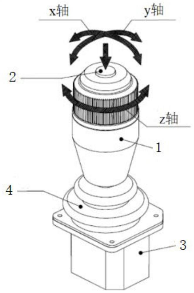
[0038] Specifically, the schematic diagram of the rocker handle (the first three-degree-of-freedom rocker handle and the second three-degree-of-freedom rocker handle) of the embodiment of the present invention is as follows figure 1 shown. The rocker handle 1 has 3 axes, that is, a handle with 3 degrees of freedom, and its three degrees of freedom are rotation around the x-axis, rotation around the y-axis and rotation around the z-axis. The rocker handle 1 is fixed on the base bracket 3 through a hemispherical universal joint. When the rocker handle 1 is manipulated to rotate forward, backward, left and right, and axially, it can output corresponding 3-axis angle data.
[0039] The handle control method based on the Hall sensor is used to realize non-contact rocker data sensing, which reduces the impact on the service life of the handle due to contact and movement wear. It has the characteristics of high sensitivity and good performance, making the operation of the handle mechanism easier. It is flexible and improves the service life of the handle; it adopts the way of cooperative control of both hands, and uses two three-degree-of-freedom handles to simulate the driving environment of the real excavator, which is conducive to achieving a good remote control effect and improving the operator's presence in the remote operation process Fully consider the driver's operating habits, control the walking and working of the excavator through the combination of different degrees of freedom of the left and right handles, simulate the joystick of the real excavator in terms of structure, freedom of movement and working range, and restore the excavator Human-computer interaction environment for driving.
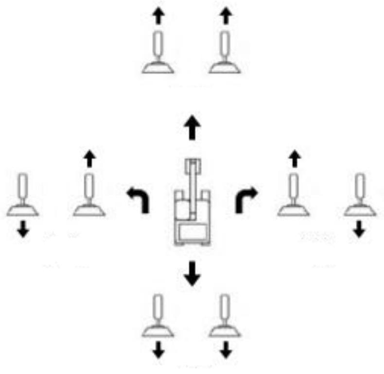
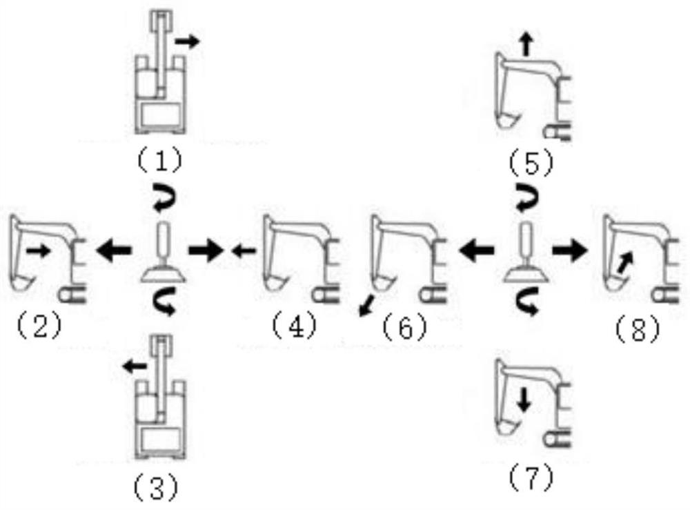
[0040] The first three degrees of freedom rocker handle, the second three degrees of freedom rocker handle and the control scheme of the two-hand cooperative operation are as follows: figure 2 and image 3 shown. in figure 2 It is a schematic diagram of the combination of two rocker handles to control the direction of the excavator, image 3 It is a schematic diagram of controlling the shovel lever and bucket of the excavator with two rocker handles. When the two handles are pushed forward or backward at the same time, the excavator is controlled to move forward or backward. When the two handles are forward and backward, the excavator is controlled to turn left or Turn right, while the left and right pushes and clockwise and counterclockwise rotations of the left handle control the bucket and body of the excavator respectively, and the left and right pushes and clockwise and counterclockwise rotations of the right handle respectively control the bucket and boom, image 3 Among them, (1) means that the car body rotates clockwise, (2) means that all dare to shrink, (3) means that the car body rotates counterclockwise, (4) means that the arm is extended, (5) means that the boom is raised, and (6) means The bucket is open, (7) indicates that the boom is lowered, and (8) indicates that the bucket is closed.
[0041] On the basis of the above embodiments, as a preferred implementation manner, the first three-degree-of-freedom rocker handle and the second three-degree-of-freedom rocker handle are respectively connected with hemispherical universal joints; the base bracket The upper sleeve is provided with a return spring, and the hemispherical universal joint is connected with the return spring.
[0042] A return spring is installed below the hemispherical universal joint around the support, and a sealing ring 4 is arranged outside the return spring. When the user manipulates the joystick handle 1, the continuous control of 3 degrees of freedom can be conveniently realized through the hemispherical universal joint. During the control process, the control in the directions of front, rear and left and right (corresponding to the x and y axes respectively) will cause pressure on the reset , so as to ensure that the handle will return to the initial vertical position after the control force is released.
[0043] On the basis of the above embodiments, as a preferred implementation manner, a first button (such as figure 1 The button 2 of the middle mark, the top of the second three-degree-of-freedom rocker handle is provided with a second button.
[0044] In order to expand the functions of the handle, the top of the joystick handle is designed with a button input function, and the user can press the button while manipulating the joystick handle to realize complex control functions.
[0045] On the basis of the above embodiments, as a preferred implementation manner, the handle controller includes an interrupt processor, and the Hall sensor, the first button and the second button are connected to an interrupt processor; The interrupt processor is used for detecting the data of the hall sensor, the first button and the second button through an interrupt I/O interrupt.
[0046] On the basis of the above embodiments, as a preferred implementation manner, the handle controller reads the first three-axis data and the second three-axis data collected by the Hall sensor through regular sampling. , and pack after filtering and calibration, and send to the host computer through USB communication;
[0047] The handle controller is used to transfer the first three-axis data, the second three-axis data and/or Or the data of the first button and/or the data of the second button are sent to the host computer.
[0048] The control software flow chart of the handle controller is as follows: Figure 4 shown. The joystick system software mainly realizes the data collection, data processing and calculation of the button data and the 3-axis data of the joystick handle, and realizes the data transmission with the host computer through USB (Universal Serial Bus, Universal Serial Bus) communication. Among them, the initialization setting mainly implements the internal register setting of the controller, setting the system clock frequency, timer setting, external I/O port setting, communication mode, communication rate, SPI (Serial Peripheral Interface, serial peripheral interface) parameter initialization and interrupt Relevant settings, etc.; data collection of function buttons (first button, second button) and 3-axis angles are realized through interrupt processing programs; wherein buttons are detected through external I/O interrupts. When a button is pressed, enter the external interrupt to detect the specific button state. The controller reads the 3-axis data inside the Hall sensor through timing sampling. After the controller successfully obtains the sensor data, it processes and packages the data and sends it out through USB communication. Among them, the button data information can be transmitted directly, but the 3-axis data of the joystick handle needs to be filtered and calibrated before transmission.
[0049] On the basis of the above embodiments, as a preferred implementation manner, the Hall sensor uses separate SPI signal lines, and the SPI signal lines include MOSI lines, MISO lines, SS lines and SCLK lines.
[0050] The schematic diagram of the hardware circuit of the handle controller is as follows: Figure 5 shown. The controller is connected to the Hall sensor through the SPI interface. The Hall sensor uses the full-duplex SPI protocol, so separate SPI signal lines are used: MOSI line, MISO line, SS line and SCLK line. The key input is a digital signal. When the button is pressed, the I/O port connected to the button will receive a low-level signal, and the program will make corresponding processing. During the working process, the handle control main program will monitor the state changes of sensors and buttons in real time, and when the state changes, it will send data to the host computer through USB communication, and will not send data if the state does not change.
[0051] On the basis of the above embodiments, as a preferred implementation manner, a depressurization module is further included, and the depressurization module is connected to the handle controller.
[0052] An excavator handle control system for remote operation provided by an embodiment of the present invention adopts a handle control method based on a Hall sensor to realize non-contact rocker data sensing and reduce the impact on the service life of the handle due to contact and movement wear. It has the characteristics of high sensitivity and good performance, which makes the operation of the handle mechanism more flexible and improves the service life of the handle; adopts the method of two-hand cooperative control, using two three-degree-of-freedom handles to simulate the driving environment of a real excavator, It is conducive to achieving a good remote control effect and improving the operator's sense of presence during remote operation; fully considering the driver's operating habits, through the combination of different degrees of freedom of the left and right handles, the walking and working of the excavator are controlled separately. Simulate the joystick of a real excavator in terms of freedom of movement, freedom of movement and working range, and restore the human-computer interaction environment of excavator driving.
[0053] Various embodiments of the present invention can be combined arbitrarily to achieve different technical effects.
[0054] In the above embodiments, all or part of them may be implemented by software, hardware, firmware or any combination thereof. When implemented using software, it may be implemented in whole or in part in the form of a computer program product. The computer program product includes one or more computer instructions. When the computer program instructions are loaded and executed on the computer, the processes or functions according to the present application will be generated in whole or in part. The computer can be a general purpose computer, a special purpose computer, a computer network, or other programmable devices. The computer instructions may be stored in or transmitted from one computer-readable storage medium to another computer-readable storage medium, for example, the computer instructions may be transmitted from a website, computer, server or data center Transmission to another website site, computer, server, or data center by wired (eg, coaxial cable, optical fiber, DSL) or wireless (eg, infrared, wireless, microwave, etc.) means. The computer-readable storage medium may be any available medium that can be accessed by a computer, or a data storage device such as a server or a data center integrated with one or more available media. The available medium may be a magnetic medium (eg, floppy disk, hard disk, magnetic tape), an optical medium (eg, DVD), or a semiconductor medium (eg, SolidState Disk).
[0055] Those of ordinary skill in the art can understand that all or part of the processes in the methods of the above embodiments are realized. The processes can be completed by computer programs to instruct related hardware. The programs can be stored in computer-readable storage media. When the programs are executed , may include the processes of the foregoing method embodiments. The aforementioned storage medium includes: ROM or random access memory RAM, magnetic disk or optical disk, and other various media that can store program codes.
[0056] Finally, it should be noted that: the above embodiments are only used to illustrate the technical solutions of the present invention, rather than to limit them; although the present invention has been described in detail with reference to the foregoing embodiments, those of ordinary skill in the art should understand that: it can still be Modifications are made to the technical solutions described in the foregoing embodiments, or equivalent replacements are made to some of the technical features; and these modifications or replacements do not make the essence of the corresponding technical solutions deviate from the spirit and scope of the technical solutions of the various embodiments of the present invention.

PUM

no PUM

Description & Claims & Application Information

We can also present the details of the Description, Claims and Application information to help users get a comprehensive understanding of the technical details of the patent, such as background art, summary of invention, brief description of drawings, description of embodiments, and other original content. On the other hand, users can also determine the specific scope of protection of the technology through the list of claims; as well as understand the changes in the life cycle of the technology with the presentation of the patent timeline. Login to view more.

Similar technology patents

Gesture recovery and recognition method based on time domain Doppler effect

InactiveCN103793059Ahigh sensitivityReduce hardware complexity
Owner:ZHEJIANG UNIV

Carbon-based resistive flexible pressure sensor

InactiveCN106595916Ahigh sensitivityWide measurement range
Owner:EAST CHINA NORMAL UNIVERSITY

Classification and recommendation of technical efficacy words

  • high sensitivity
  • good performance

System and method for optical coherence imaging

ActiveUS20060055936A1sufficient signal to noise ratiohigh sensitivity
Owner:THE GENERAL HOSPITAL CORP

Three-axis integrated MEMS accelerometer

InactiveUS20060272413A1low costhigh sensitivity
Owner:VAGANOV VLADIMIR +1

Capacitive micromachined acoustic transducer

ActiveUS20060233401A1wide bandwidthhigh sensitivity
Owner:NEOMEMS TECH INC WUXI CHINA

Patterning process, resist composition, and acetal compound

InactiveUS20110236826A1high dissolution contrasthigh sensitivity
Owner:SHIN ETSU CHEM CO LTD

Motion sensor and analysis

InactiveUS20150019135A1good performance
Owner:MC 10 INC

Macrocyclic picolinamides as fungicides

ActiveUS20140187588A1good performanceeasy to use
Owner:CORTEVA AGRISCIENCE LLC

System and Method for Socially Aware Recommendations Based on Implicit User Feedback

InactiveUS20150187024A1good performanceintroduce noise
Owner:TELEFONICA DIGITAL ESPANA S L U
Why Eureka
Try Eureka