Method for formulating vibration limit value of aeronautical transmission system

A transmission system and limit value technology, applied in the field of transmission system, can solve problems such as insufficient precision, fatigue, transmission system correlation deviation, etc., and achieve the effect of accurate results, precise results and precise load spectrum

Active Publication Date: 2021-08-06
CHONGQING UNIV +1
View PDF13 Cites 2 Cited by
  • Summary
  • Abstract
  • Description
  • Claims
  • Application Information

AI Technical Summary

Problems solved by technology

[0008](1) Existing methods for determining vibration limit values ​​require a large number of destructive tests to obtain vibration values, which are very expensive in terms of manpower, material resources, financial resources and time
[0009](2) There are relevant domestic experience standards such as GB / T 6075 "Measurement and Evaluation of Mechanical Vibration on Non-rotating Parts" series of standards, etc. or foreign related standards Standards such as the API standard tutorial (API 684 Rotor dynamic Tutorial: Lateral Critical Speeds) issued by the American Petroleum Institute on the vibration, balance and stability analysis of rotating machinery, etc., but there are deviation factors related to the actual transmission system, which may not be applicable to new machines In the case of different models, if the transmission system limit value determined from this is too large or too small, it will cause the transmission system to fail to reach the expected life and cause fatigue and damage.
Due to the large error in the vibration test of each rotor alone and the vibration test of each rotor coupling system, additional mode shapes, vibrations, etc. will be generated after coupling, which cannot represent the vibration under normal working conditions of the engine. The vibration limit determined by this The value has the limitations of not considering coupling factors and insufficient precision

Method used


Image

  • Method for formulating vibration limit value of aeronautical transmission system
  • Method for formulating vibration limit value of aeronautical transmission system
  • Method for formulating vibration limit value of aeronautical transmission system

Examples


Embodiment 1

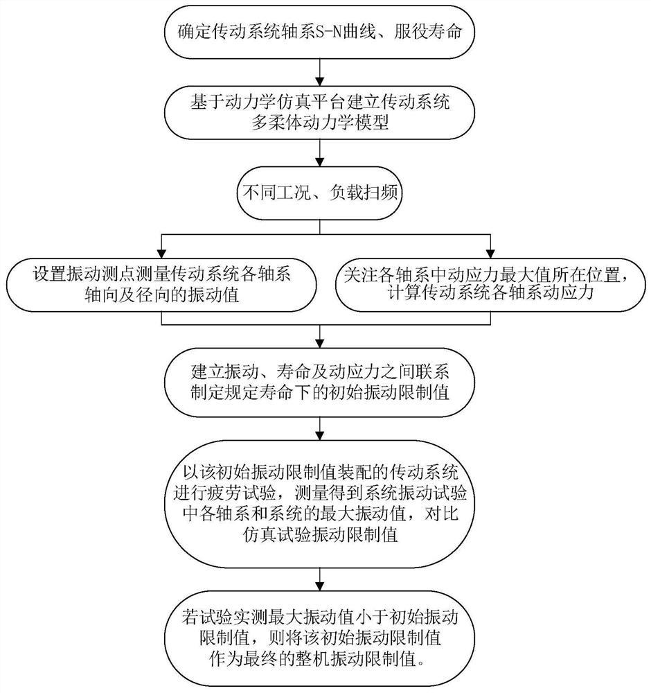
[0051] This embodiment discloses a method for formulating the vibration limit value of the aviation transmission system, see figure 1 , including the following steps:

[0052] 1) Determine the life value of the aviation transmission system and the S-N curve of the material. The aviation transmission system should have a definite service life value when designing, and the material S-N curve is the basis for evaluating the fatigue life of the research object. During the loading process, the mechanical structure bears alternating stress in different positions and directions. It is generally believed that the cyclic stress has a linear relationship with the fatigue life of the material. That is, the smaller the stress, the longer the structural life; the greater the stress, the shorter the structural life. In this embodiment, a cyclic load test is carried out on each transmission part of the aviation transmission system, and the service life of each transmission part is recorded...

Embodiment 2

[0091] This embodiment provides a relatively basic implementation method, a method for formulating the vibration limit value of the aviation transmission system, see figure 1 , including the following steps:

[0092] 1) Determine the life value of the aviation transmission system and the S-N curve of the material. The aviation transmission system should have a definite service life value when designing, and the material S-N curve is the basis for evaluating the fatigue life of the research object. During the loading process, the mechanical structure bears alternating stress in different positions and directions. It is generally believed that the cyclic stress has a linear relationship with the fatigue life of the material. That is, the smaller the stress, the longer the structural life; the greater the stress, the shorter the structural life. In this embodiment, a cyclic load test is carried out on each transmission part of the aviation transmission system, and the service l...

Embodiment 3

[0118] The main steps of this embodiment are the same as in Example 2, further, in step 4.1), the stress ratio R i The formula is calculated as follows:

[0119]

[0120] In formula (1), σ mi is the mean stress, σ ai is the stress amplitude.


PUM


Abstract

The invention discloses a method for formulating a vibration limit value of an aeronautical transmission system. The method comprises the following steps: 1) determining a life value of the aeronautical transmission system and an S-N curve of a material; 2) establishing a multi-flexible dynamic model of the aeronautical transmission system; 3) measuring vibration values of each shafting of the aeronautical transmission system under different working conditions and load conditions, and calculating dynamic stress and load of each shafting of the aeronautical transmission system along with time history; 4) compiling a load spectrum based on the load of each shafting of the aeronautical transmission system along with the time history; 5) calculating the service life of each shafting of the aeronautical transmission system under different working conditions and load conditions; 6) establishing a coupling relation between the vibration values and the service life of each shafting of the aeronautical transmission system under different working conditions and load conditions. According to the method for formulating the limit value through combination of simulation and tests, a large number of tests are avoided, and the cost of time, manpower, material resources and the like is saved.

Description

technical field [0001] The invention belongs to the technical field of transmission systems, and in particular relates to a method for formulating vibration limit values ​​of aviation transmission systems. Background technique [0002] The vibration source of the transmission system mainly comes from structural design, manufacturing, installation, commissioning and the environment itself. Vibration can cause structural fatigue and damage in a very short period of time. Therefore, in the vibration design, attention must be paid to the fatigue damage of each gear shaft of the transmission system. However, determining the vibration limit value has always been a relatively difficult problem. [0003] Regarding vibration limiting parameters—displacement, velocity, and acceleration, each parameter has a clear physical concept. Limiting displacement is to control the amplitude of vibration, limiting vibration speed is to control vibration energy, and limiting vibration acceleratio...

Claims


Application Information

Patent Timeline
Patent Type & Authority Applications(China)
IPC IPC(8): G06F30/17G06F30/15G06F30/20G06F30/23G06F119/14
CPCG06F30/17G06F30/15G06F30/20G06F30/23G06F2119/14Y02T90/00
Inventor 魏静程浩张爱强颜强李良祥陈向前
Owner CHONGQING UNIV
Why Eureka
Try Eureka