Motor lumped parameter model modeling method
A technology of centralized parameter models and modeling methods, which is applied in special data processing applications, design optimization/simulation, etc., can solve the problems of inability to effectively respond to motor saturation, harmonics, inability to guarantee inductance curves, smooth flux linkage curves, and influence on motor models Solve problems such as efficiency and convergence performance, to achieve the effect of improving solution efficiency and convergence performance, and improving model accuracy
- Summary
- Abstract
- Description
- Claims
- Application Information
AI Technical Summary
Problems solved by technology
Method used
Image
Examples
Embodiment 1
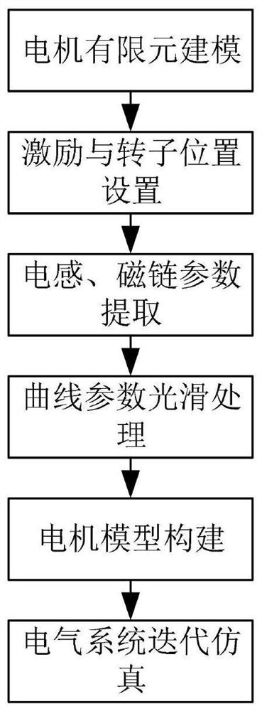
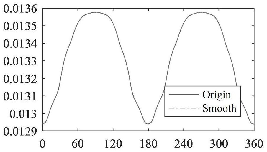
[0025] Example 1: See figure 1 , Figure 2a and Figure 2b , the present invention provides a technical solution: a motor centralized parameter model modeling method, comprising the following steps:
[0026] S1. According to the motor structure parameters, construct the motor finite element model; the motor structure parameters in the step S1 include the motor stator and rotor punching structure parameters, winding arrangement parameters, magnetic steel structure parameters and boundary conditions;
[0027] S2. Set the stator and rotor excitation parameters and rotor position, and calculate the finite element model; set the maximum scan angle according to the motor type, phase number, and pole pair number, for example, for a three-phase permanent magnet synchronous motor, you can set the maximum scan angle of the rotor Then, construct the flux linkage and inductance curves according to the odd harmonic function characteristics of the flux linkage and inductance; take into ac...
Embodiment 2
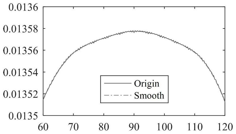
[0035] Example 2: see figure 1 , Figure 3a and Figure 3b , the present invention provides a technical solution: a motor centralized parameter model modeling method, comprising the following steps:
[0036] S1. According to the motor structure parameters, construct the motor finite element model; the motor structure parameters in the step S1 include the motor stator and rotor punching structure parameters, winding arrangement parameters, magnetic steel structure parameters and boundary conditions;
[0037] S2. Set the stator and rotor excitation parameters and rotor position, and calculate the finite element model; set the maximum scanning angle according to the motor type, phase number, and pole pair number; then, construct each Flux linkage and inductance curves; scan different current combinations of windings; when scanning multi-phase winding motors or squirrel cage bars, use equivalent current vectors to scan;
[0038] S3. Extract the inductance and flux linkage param...
PUM
 Abstract
Description
Claims
Application Information
 - R&D
- Intellectual Property
- Life Sciences
- Materials
- Tech Scout
- Unparalleled Data Quality
- Higher Quality Content
- 60% Fewer Hallucinations
Browse by: Latest US Patents, China's latest patents, Technical Efficacy Thesaurus, Application Domain, Technology Topic, Popular Technical Reports.
© 2025 PatSnap. All rights reserved.Legal|Privacy policy|Modern Slavery Act Transparency Statement|Sitemap|About US| Contact US: help@patsnap.com


