Contactless guide rail dedusting device

A dust removal device and non-contact technology, applied in the field of machine tool guide rails, can solve the problem of large occupation of protective cover space, and achieve the effects of reducing the difficulty of processing and manufacturing, reducing product models, and reducing production costs.

Inactive Publication Date: 2021-08-10
洛阳广纬精工科技有限公司
View PDF6 Cites 0 Cited by
  • Summary
  • Abstract
  • Description
  • Claims
  • Application Information

AI Technical Summary

Problems solved by technology

For long-travel guide rails, the protective cover takes up a lot of space

Method used


Image

  • Contactless guide rail dedusting device
  • Contactless guide rail dedusting device
  • Contactless guide rail dedusting device

Examples


Embodiment 1

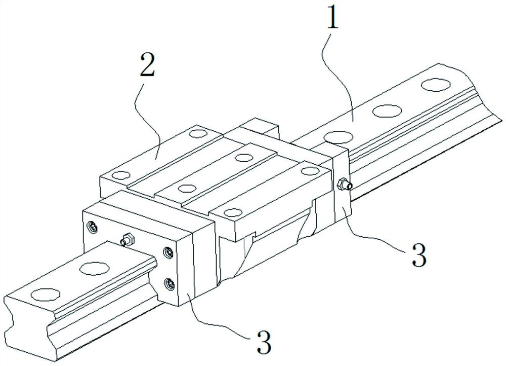
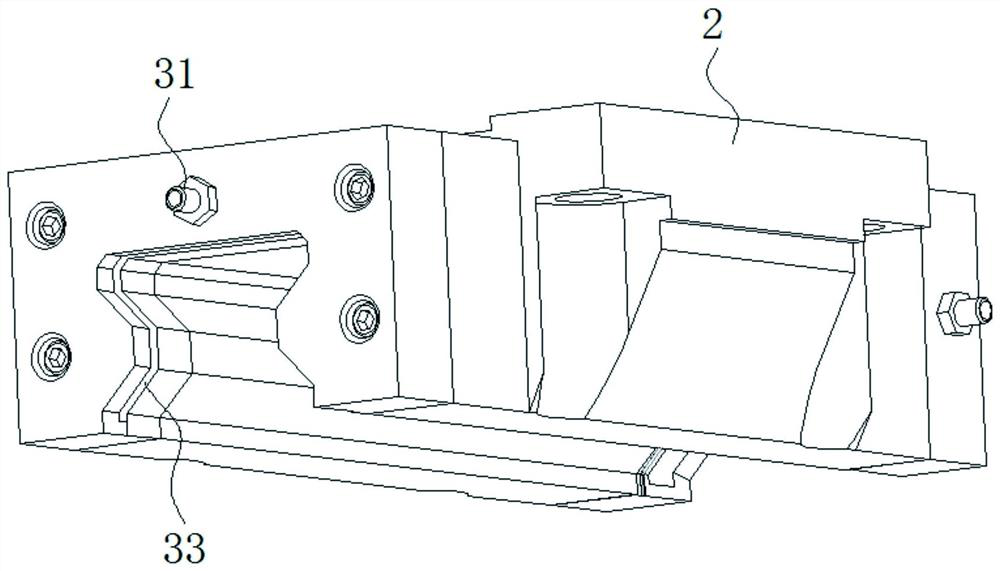
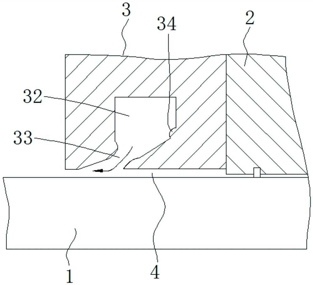
[0028] A non-contact guide rail dust removal device, such as Figure 1-3 As shown, as an optional accessory of the guide rail slider assembly, it is installed on the end face of the slider 2 and forms a groove-shaped gap 4 equidistant from the working surface of the guide rail. The guide rail dedusting device 3 is provided with an air inlet 31 , an air chamber 32 and an air injection port 33 . Specific instructions are given below.

[0029] Such as image 3 As shown, the air inlet 31 is connected to an air source through a reversing valve, and is used for introducing high-pressure air into the air cavity 32 . The air injection port 33 has a shape suitable for the cross-sectional shape of the guide rail, and forms an equidistant groove-shaped slit 4 with the special-shaped working surface of the guide rail, and the slit width of the groove-shaped slit is 0.15mm. Since the air jet has a closing structure, the flow rate of high-pressure air can be further increased. The air i...

Embodiment 2

[0036] Different from Example 1, as Figure 5 As shown, the guide rail dedusting device 3 is composed of two split parts connected by bolts. A gasket 5 is additionally installed between the two split parts, and the gasket 5 is used to adjust the slit width of the air outlet side of the slot-shaped slit 4 . Such a design, firstly, realizes the adjustment of the groove-shaped gap 4; secondly, separate processing reduces the processing difficulty of the air cavity 32 and the air injection port 33 . Obviously, such a design does not require mold opening, which is beneficial to the small-batch machining production of the present invention.

[0037] In the above two embodiments, although the air consumption of the guide rail dedusting device 3 is not large, the total air consumption is still very large in the case of a long working time. Therefore, the technical solution is further improved: the air inlet 31 on each rail dedusting device 3 is connected to the air source through a ...


PUM


Abstract

The invention relates to a contactless guide rail dedusting device which is mounted on an end surface of a slide block as an optional accessory of a guide rail slide block and forms an isometric slotted gap with a working surface of the guide rail. The guide rail dedusting device is provided with an air inlet, an air cavity and an air jet hole, wherein the air jet hole is provided with a close-up structure capable of improving the flow rate of a gas, inclines to the slotted gap to blow away dust particles attached to the guide rail outwards, and generates a negative pressure at the inner side end close to the slide block of the slotted gap. The device has the beneficial effects that 1, the device is not contact with the guide rail all the time, is not attached with dust, is good in dedusting effect and has a long effect; 2, the attaching amount of the dust particles on the guide rail is reduced, and the damage to the guide rail by the iron-containing dust particles is reduced; 3, the processing and manufacturing difficulty is reduced; 4, the consumption of high pressure air is reduced greatly; 5, it is favorable to eliminate impurity particles in a matching surface of the guide rail slide block outwards and enter a lubricating liquid; and 6, the demand of a machine tool on a guide rail protecting hood is reduced.

Description

technical field [0001] The invention relates to the technical field of machine tool guide rails, in particular to a non-contact guide rail dust removal device. Background technique [0002] In the machine tool industry, a large number of guide rails need to be used as guide supports for component movement. In order to protect the guide rails from premature wear, most guide rails are equipped with protective covers to prevent iron filings or other abrasive particles from falling on the guide rails. Practice has proved that large particles of iron filings cannot enter the mating surface of the guide rail and will not cause wear to the guide rail, while tiny dust particles can enter the mating surface of the guide rail and cause the greatest wear on the guide rail. Most of the existing protective covers are semi-open and have no protective effect on dust particles floating in the air. Even a fully enclosed protective cover cannot completely isolate the air, and it is difficult...

Claims


Application Information

Patent Timeline
Patent Type & Authority Applications(China)
IPC IPC(8): B08B5/02B08B13/00B23Q1/01B23Q11/00
CPCB08B5/02B08B13/00B23Q1/017B23Q11/005
Inventor 陈建立王志刚崔攀峰
Owner 洛阳广纬精工科技有限公司
Why Eureka
Try Eureka