
Fixed clamping structure facilitating stamping machining

A technology of fixed clamping and stamping processing, which is applied in the field of stamping processing, and can solve the problems of not having metal parts, not reaching the accuracy of stamping processing, and reducing work efficiency.

Active Publication Date: 2021-08-10
江门市联宝电器有限公司
View PDF8 Cites 0 Cited by
  • Summary
  • Abstract
  • Description
  • Claims
  • Application Information

AI Technical Summary

Problems solved by technology

[0004] The purpose of the present invention is to solve the following shortcomings in the prior art. Most of the existing stamping machines do not have clamping and fixing devices for metal parts, so that during the stamping process, the metal parts placed on the stamping machine are subject to the force of the machine. Vibration, prone to offset, resulting in the inability to perform accurate stamping processing, not only failing to achieve the accuracy of stamping processing, but also reducing work efficiency, and a fixed clamping structure that is convenient for stamping processing is proposed

Method used


Image

  • Fixed clamping structure facilitating stamping machining
  • Fixed clamping structure facilitating stamping machining
  • Fixed clamping structure facilitating stamping machining

Examples


Embodiment Construction

[0023] The following will clearly and completely describe the technical solutions in the embodiments of the present invention with reference to the accompanying drawings in the embodiments of the present invention. Obviously, the described embodiments are only some, not all, embodiments of the present invention.

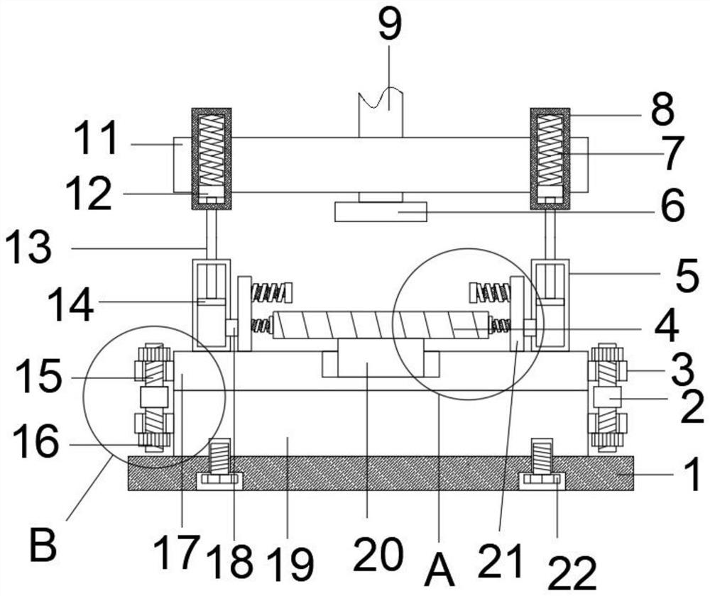
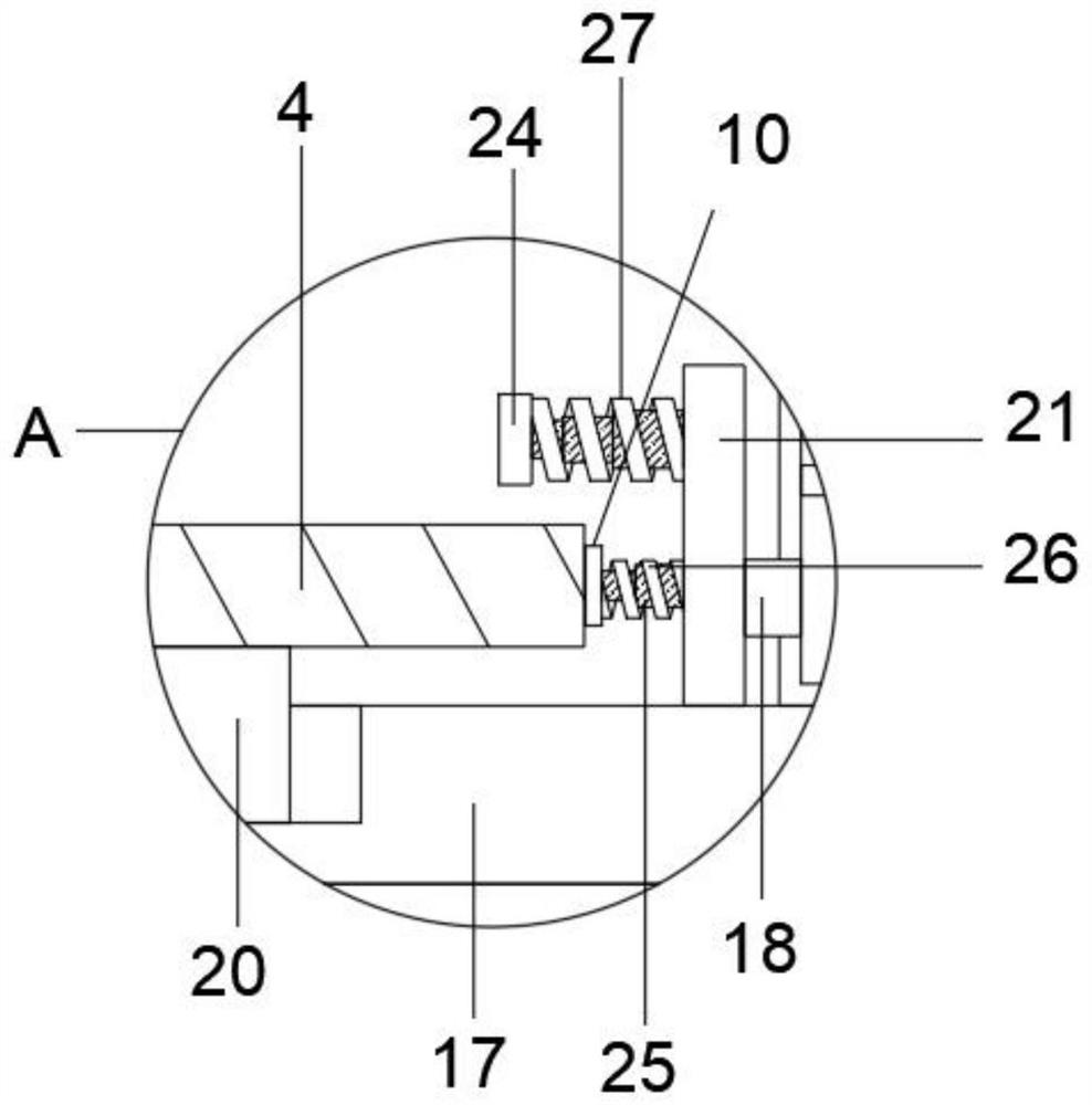
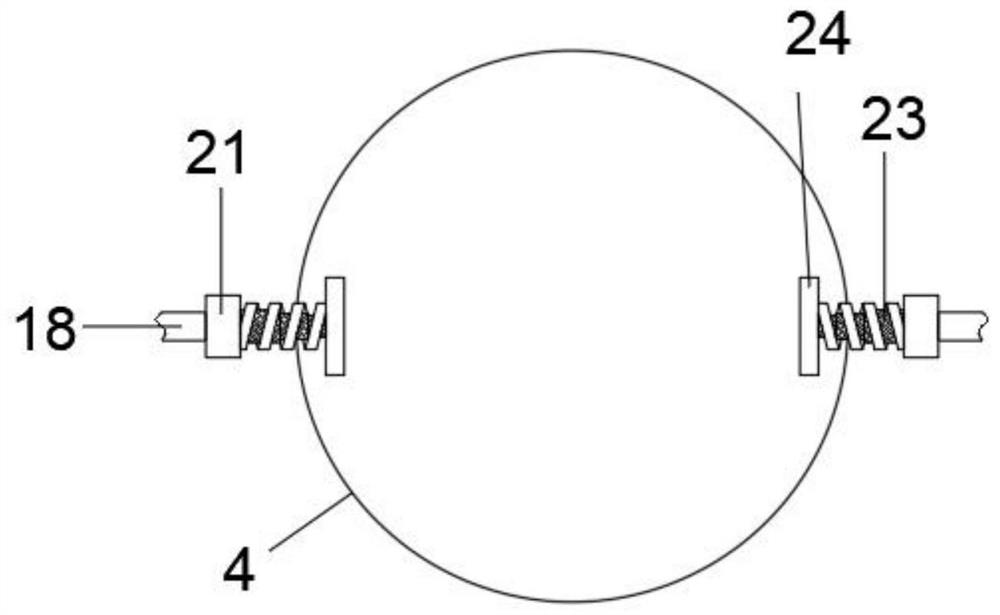
[0024] refer to Figure 1-4 , a kind of fixed clamping structure that is convenient for stamping process, comprises base 1, and base 1 is provided with fixed plate 19, and the end of fixed plate 19 away from base 1 is provided with lower pressure plate 17, and fixed plate 19 two ends are respectively fixedly connected with second The threaded sleeve 28, the first threaded sleeve 3 is fixedly connected to the two sides of the lower pressure plate 17 respectively, the rotating ring 2 is arranged between the first threaded sleeve 3 and the second threaded sleeve 28, the upper end of the rotating ring 2 is fixedly connected with the upper screw rod 15, and the upper end o...


PUM


Abstract

The invention discloses a fixed clamping structure facilitating stamping machining. The fixed clamping structure comprises a base, wherein a fixed plate is arranged on the base, a lower pressing plate is arranged at the end, away from the base, of the fixed plate, a supporting column is rotationally connected to the end, away from the fixed plate, of the lower pressing plate, a bearing platform is fixedly connected to the upper end of the supporting column, sealing cavities are fixedly connected to the two ends of the lower pressing plate respectively, sealing plugs are slidably connected into the sealing cavities, and air cavities are formed between the two sealing cavities and the bearing platform and fixedly connected to the lower pressing plate. Gas in the air cavities enters into a first telescopic cavity and a second telescopic cavity through extrusion to form the extension of the first telescopic cavity and the second telescopic cavity, and the metal part placed on the bearing platform and the bearing platform are clamped and fixed, so that the phenomenon that the metal part needing to be machined deviates when vibration is generated during work of the punching machine is avoided.

Description

technical field [0001] The invention relates to the technical field of stamping, in particular to a fixed clamping structure for stamping. Background technique [0002] Stamping is to rely on presses and molds to apply external force to plates, strips, pipes and profiles, etc., to cause plastic deformation or separation, so as to obtain workpieces (stamping parts) of required shape and size. Stamping and forging belong to Plastic processing (or pressure processing), collectively known as forging. Stamping blanks are mainly hot-rolled and cold-rolled steel sheets and strips. Among the steel products in the world, 60-70% are sheets, most of which are stamped into finished products, such as car bodies, chassis, fuel tanks, and radiator fins. , The steam drum of the boiler, the shell of the container, the iron core silicon steel sheet of the motor and electrical appliances, etc. are all stamped. There are also a large number of stamped parts in products such as instruments and ...

Claims


Application Information

Patent Timeline
IPC IPC(8): B21D37/04B21D43/00
CPCB21D37/04B21D43/003
Inventor 陈峥
Owner 江门市联宝电器有限公司
Learn More