Tool and equipment for disassembling and assembling tuyere medium sleeve of iron-making blast furnace

A tuyere-in-sleeve, iron-making blast furnace technology, applied in tuyere, lifting devices, manufacturing tools, etc., can solve problems such as the structural strength, service life and stability of the installation machine head itself, the tuyere mid-sleeve falling off, and potential safety hazards. , to achieve the effect of improving the clamping and fixing effect, improving the supporting effect and reducing the labor intensity

Active Publication Date: 2021-08-10
济南华北升降平台制造有限公司
View PDF23 Cites 1 Cited by
  • Summary
  • Abstract
  • Description
  • Claims
  • Application Information

AI Technical Summary

Problems solved by technology

However, due to the structural characteristics of the tuyere middle sleeve itself, such as heavy weight and large size, when the tuyere middle sleeve is operated by the above-mentioned installation machine, the large-diameter end of the tuyere middle sleeve will be inclined downward under the action of its own gravity and against it. Lean on the head of the installer
In this way, during the moving process of the installation machine, the head of the installation machine cannot realize the stable positioning of parts such as the tuyere middle sleeve. Shaking occurs due to the rotation or shaking of the machine. In severe cases, it may cause the tuyere middle sleeve to fall off from the head of the installation machine and cause unnecessary safety hazards.
Moreover, if the middle sleeve of the tuyere rests against the head of the installation machine for a long time, it will also have a great impact on the structural strength, service life and stability of the head of the installation machine.

Method used


Image

  • Tool and equipment for disassembling and assembling tuyere medium sleeve of iron-making blast furnace
  • Tool and equipment for disassembling and assembling tuyere medium sleeve of iron-making blast furnace
  • Tool and equipment for disassembling and assembling tuyere medium sleeve of iron-making blast furnace

Examples


example 1

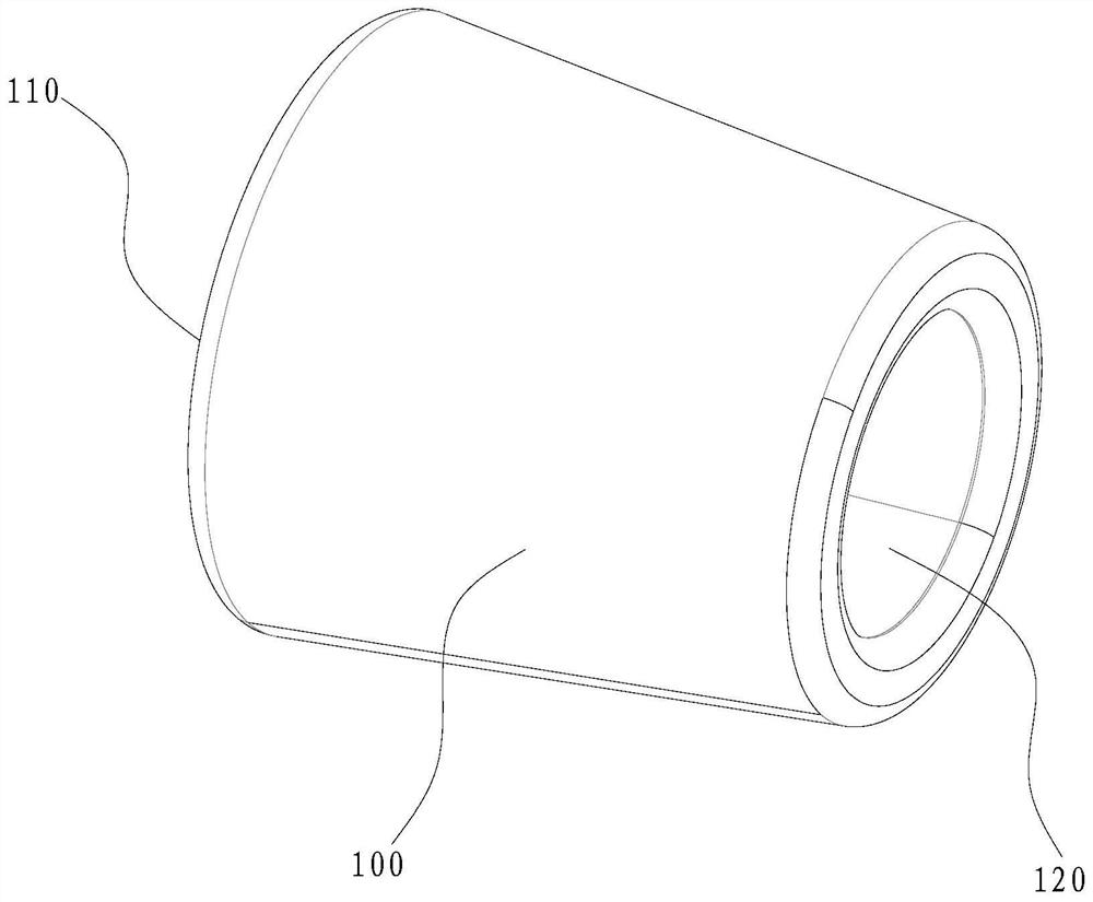
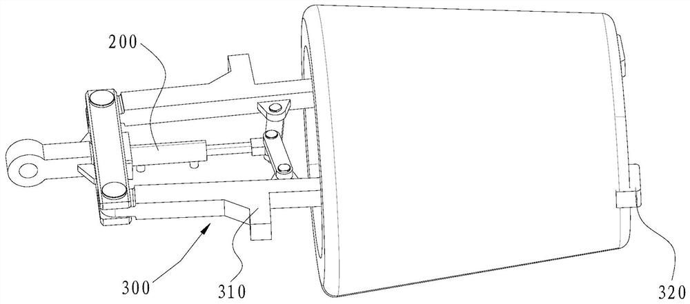
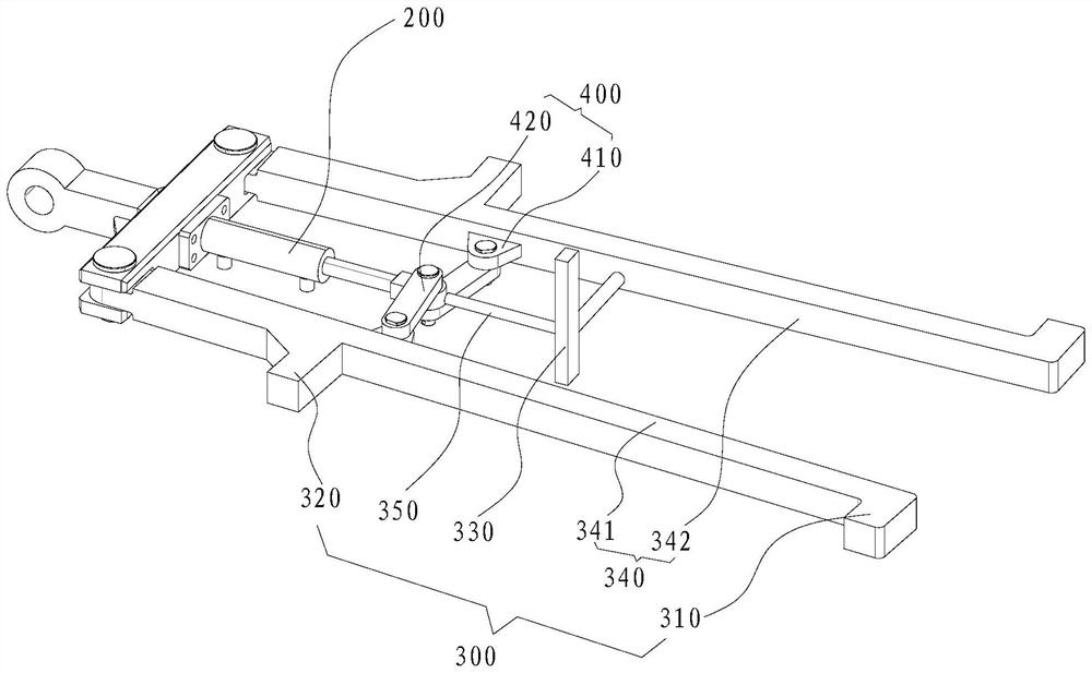
[0050] refer to image 3 As shown, the grabbing device 300 in this example may include a clamping arm 340, the support member 330 is rotatably disposed on the clamping arm 340, and the support member 330 has an inner wall against the inner sleeve 100 of the tuyere. The support state is connected and the release state is separated from the inner wall of the sleeve 100 in the tuyere.

[0051] The supporting member 330 is rotatably disposed on the clamping arm 340 so that the supporting member 330 can rotate relative to the clamping arm 340 so that the supporting member 330 has a supporting state and a releasing state. In the supported state, the support member 330 can support the tuyere middle cover 100, and avoid the possibility of the tuyere middle cover 100 shaking to the greatest extent; Separated and rotated to a suitable position to provide convenience for subsequent disassembly and assembly actions, it can also make the material space occupied by the grabbing device 300 ...

example 2

[0057] refer to Figure 4 As shown, the difference between the second example and the first example above is that the clamping arm 340 is provided with an elastic member 343 and a slider 344, wherein the slider 344 is connected with the elastic member 343 and the connecting rod in the grabbing device 300 respectively. 350 are connected, and the connecting rod 350 can make the sliding block 344 slide back and forth along the clamping arm 340 under the driving action of the driving device 200 .

[0058] When the grabbing device 300 is in the locked position, the slider 344 abuts against the bottom of the support 330, so that the support 330 stands up to be in a supporting state; when the grabbing device 300 is in the unlocked position, the slider 344 is in contact with the support The supporting part 330 is separated, and the supporting part 330 returns to the horizontal under the elastic force of the elastic part 343 so that it is in a released state.

[0059] It should be not...

Embodiment approach

[0062] As a preferred embodiment of the present invention, the car body 500 may also include a gantry frame 520, the gantry frame 520 is provided with a transverse guide rail 521 and a vertical guide rail 522, and the rotating seat 510 and the vertical guide rail 522 for sliding fit, so that the tooling moves up and down along the gantry 520;

[0063] The equipment provided by this application for disassembling and assembling the tuyeres of ironmaking blast furnaces enables the tooling to have a variety of different motion states relative to the car body 500 , so that the tooling can be lifted to disassemble and assemble the tuyeres 100 in different positions or postures , so that the equipment has a wider environmental adaptability, and provides convenience for the actual work process of workers.

[0064] The places not mentioned in the present invention can be realized by adopting or referring to the prior art.


PUM


Abstract

The invention discloses a tool and equipment for disassembling and assembling a tuyere medium sleeve of an iron-making blast furnace. The tool comprises a driving device and a grabbing device connected with the driving device. Under the driving action of the driving device, the grabbing device is provided with a locking position opened to clamp the inner wall of the tuyere medium sleeve and an unlocking position contracted to release the tuyere medium sleeve. The end, away from the driving device, of the grabbing device is provided with a first stop piece capable of being clamped with a first opening edge of the tuyere medium sleeve, and the other end, close to the driving device, of the grabbing device is provided with a second stop piece capable of being clamped with a second opening edge of the tuyere medium sleeve. The grabbing device is further provided with a supporting piece, and the supporting piece can abut against the inner wall of the tuyere medium sleeve when the supporting piece is located at the locking position so that the tuyere medium sleeve can be prevented from shaking in the moving process. The clamping and fixing effect on the tuyere medium sleeve is better, so that the potential safety hazard that the tuyere medium sleeve falls off from the grabbing device is reduced.

Description

technical field [0001] The invention belongs to the technical field of disassembly and maintenance of blast furnaces, and in particular relates to a tooling and equipment for disassembly and assembly of tuyere jackets of ironmaking blast furnaces. Background technique [0002] The iron-making blast furnaces in the prior art usually consist of a blast furnace body, a feeding device, an air supply device, a gas recovery and dust removal device, a slag iron processing device, and a blowing device. Since the iron-making blast furnace is a closed high-temperature and high-pressure device, the air supply device blows hot air into the furnace through the tuyere sleeve installed on the blast furnace body. The tuyere cover generally includes a large set, a middle set and a small set. The large set is made of cast iron, the middle set and the small set are made of cast iron or cast copper, and they are all conical. The front end of the sleeve and the rear end of the small tuyere slee...

Claims


Application Information

Patent Timeline
Patent Type & Authority Applications(China)
IPC IPC(8): B66F9/06B66F9/08B66F9/14B66F9/12B66F9/18C21B7/16B25B27/00B25B11/02
CPCB66F9/06B66F9/08B66F9/14B66F9/122B66F9/149B66F9/185C21B7/16B25B27/00B25B11/02Y02P10/20
Inventor 罗殿华罗松罗佃全
Owner 济南华北升降平台制造有限公司
Why Eureka
Try Eureka