
Device for simulating light-transmitting irradiation skylight environment for house roof

A technology for houses and skylights, which is applied in the field of devices for simulating the environment of the skylight through light transmission, which can solve the problems of high cost, high technical difficulty, and complicated production process, and achieve the effect of low production cost, simple materials, and easy availability of materials

Pending Publication Date: 2021-08-10
吉林省远大光学检测技术有限公司
View PDF4 Cites 1 Cited by
  • Summary
  • Abstract
  • Description
  • Claims
  • Application Information

AI Technical Summary

Problems solved by technology

[0002] At present, the technology that can simulate sunlight and sky background light is mainly nanoparticle coating scattering technology, which coats the surface of optical materials with nanoparticle coating to form a nanoparticle coating, and illuminates the nanoparticle coating by mixing light sources to make the mixing Light and nanoparticles produce Rayleigh scattering to form blue light in the sky background, and by controlling the thickness of the nanoparticle coating, the transmittance of the mixed light is controlled to achieve the effect of sunlight lighting. This technology is difficult and costly, and The production process of the product is complex

Method used


Image

  • Device for simulating light-transmitting irradiation skylight environment for house roof
  • Device for simulating light-transmitting irradiation skylight environment for house roof
  • Device for simulating light-transmitting irradiation skylight environment for house roof

Examples


Embodiment Construction

[0052] The following will clearly and completely describe the technical solutions in the embodiments of the present invention with reference to the accompanying drawings in the embodiments of the present invention. Obviously, the described embodiments are only some of the embodiments of the present invention, not all of them. Based on the embodiments of the present invention, all other embodiments obtained by persons of ordinary skill in the art without making creative efforts belong to the protection scope of the present invention.

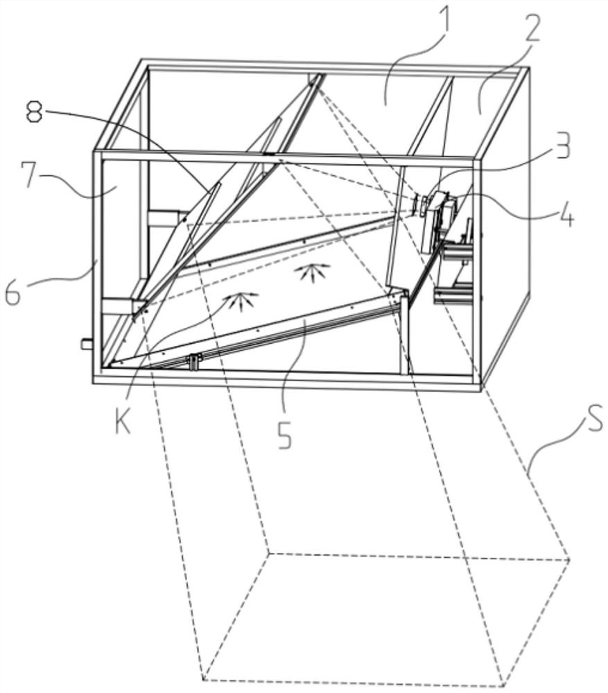
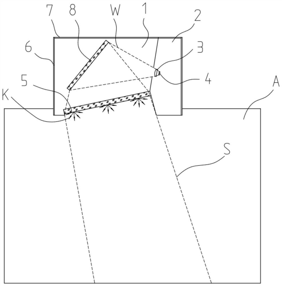
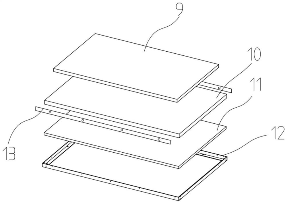
[0053] Such as Figure 1 to Figure 6 As shown, the present invention provides a device for simulating the light-transmitting irradiation skylight environment on the roof of a house, including a support frame 6, a hoarding plate 7 is fixedly installed on the periphery of the support frame 6, and a light-absorbing plate is provided on the left end and the right end of the inner side of the hoarding plate 7 respectively. Darkroom 1 and heat dissipat...


PUM

PropertyMeasurementUnit
Wavelengthaaaaaaaaaa

Abstract

The invention belongs to the technical field of light source simulation, and discloses a device for simulating a light-transmitting irradiation skylight environment for a house roof. The device comprises a supporting frame, wherein a surrounding plate is fixedly installed on the periphery of the supporting frame, a light absorption dark room and a heat dissipation room are formed in the left end and the right end of the interior of the surrounding plate respectively, a collecting lens is fixedly installed in the middle of the left end of the interior of the heat dissipation room, and a white light source is fixedly installed on the right side of the collecting lens. According to the device, by arranging the light absorption dark room, a window assembly, the white light source and the like, the purposes of good sunlight simulation effect and low manufacturing cost are achieved, the white light source emits white light and then irradiates the surface of a reflector through pretreatment of a collimating collecting lens, the reflector projects the light source to an area of the window assembly at the moment, after layer-by-layer treatment of an internal structure of the window assembly, parallel light is emitted and thrown into the room, and a blue light source emits blue light and forms soft blue scattered light after scattering treatment of nano-scale particles.

Description

technical field [0001] The invention belongs to the technical field of simulated light sources, in particular to a device for simulating the environment of a skylight illuminated by light transmission on the roof of a house. Background technique [0002] At present, the technology that can simulate sunlight and sky background light is mainly nanoparticle coating scattering technology, which coats the surface of optical materials with nanoparticle coating to form a nanoparticle coating, and illuminates the nanoparticle coating by mixing light sources to make the mixing Light and nanoparticles produce Rayleigh scattering to form blue light in the sky background, and by controlling the thickness of the nanoparticle coating, the transmittance of the mixed light is controlled to achieve the effect of sunlight lighting. This technology is difficult and costly, and The production process of the product is complex. [0003] The invention relates to a device for simulating sunlight ...

Claims


Application Information

Patent Timeline
IPC IPC(8): F21V9/02F21V13/00F21Y115/10
CPCF21V9/02F21V13/00F21Y2115/10
Inventor 张军
Owner 吉林省远大光学检测技术有限公司
Learn More