
Current source type multi-level inverter circuit, device and modulation method

A multi-level inverter, current source type technology, applied in the output power conversion device, the conversion of AC power input to DC power output, electrical components and other directions, can solve the problem of jeopardizing the stable operation of the system, the malfunction of the controller, affecting the system power quality and other issues

Active Publication Date: 2021-08-10
SHENZHEN POWER SUPPLY BUREAU
View PDF4 Cites 2 Cited by
  • Summary
  • Abstract
  • Description
  • Claims
  • Application Information

AI Technical Summary

Problems solved by technology

These power electronic devices working in non-ideal conditions will become the ripple source of the DC distribution network, which will affect the power quality of the system, and in serious cases will cause malfunction of the controller, directly endangering the stable operation of the entire system

Method used


Image

  • Current source type multi-level inverter circuit, device and modulation method
  • Current source type multi-level inverter circuit, device and modulation method
  • Current source type multi-level inverter circuit, device and modulation method

Examples


specific Embodiment approach

[0118] Take the AC current waveform with an output frequency of 120kHz and an effective current value of 2.3A as an example:

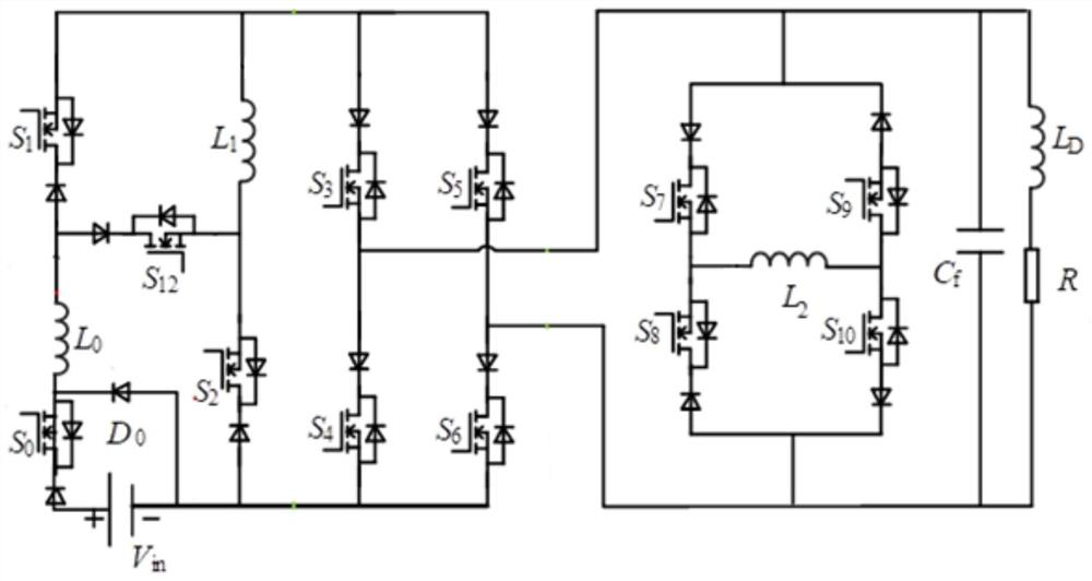
[0119] see Figure 21 , Now set the flying inductance shunt circuit as 0.5I, can realize -2.5I, -2I, -1.5I, -I, -0.5I, 0, +0.5I, +I, +1.5I, +2I, + 13-level output of 2.5I, in order to ensure that each level has a redundant switch state, only select -2I, -1.5I, -I, -0.5I, 0, +0.5I, +I, +1.5I, +2I 9 level outputs.

[0120] The effective value of the output current is 2.3A, and the peak value corresponds to the high level, which can be obtained as follows: Then the shunt inductor current is 0.5I, that is, 0.8A. The nine output levels are -3.2A, -2.4A, -1.6A, -0.8A, 0, +0.8A, +1.6A, +2.4A, +3.2A.

[0121] Apply the time zone decomposition vector modulation method to modulate as follows:

[0122] According to formula (1), the modulated wave i is reversed and compressed into a deformed modulated wave i' between 0 and 1.6A:

[0123]

[0124] in It...


PUM


Abstract

A current source type multi-level inverter circuit comprises a current doubling circuit which is used for providing reference current including first reference current or second reference current, wherein the second reference current is twice of the first reference current; an inverter bridge circuit which is connected with the current doubling circuit and is used for inverting the reference current to generate initial inverter current; and a flying inductor shunt circuit which is connected with the inverter bridge circuit and is used for outputting multi-level inverter current to a load according to the initial inverter current. Inductors in the current source type multi-level inverter circuit are relatively independent, the phenomenon of shunt of multiple inductors in parallel does not exist, the problem of uneven distribution of inductive current is avoided, and then multi-level stable inverter current is output to a load. Meanwhile, the number of levels can be easily expanded through the parallel flying inductor unit and the parallel inverter topology, the flexibility in practical application is high, and the economical efficiency is further improved.

Description

technical field [0001] The present application relates to the technical field of multilevel inverters, in particular to a current source type multilevel inverter circuit, device and modulation method. Background technique [0002] With the rapid development of science and technology, the increase of DC load and the access of distributed power supply make the DC power distribution method more and more widely used. Since there are many different types of converter devices in the DC power distribution system, such as: bidirectional AC / DC converters connected to the AC grid, bidirectional DC / DC converters connected to energy storage units, new energy power generation access DC / DC or AC / DC converters, DC / DC or AC / DC converters connected to DC / AC loads, etc. These power electronic devices working under non-ideal conditions will become the ripple source of the DC distribution network, which will affect the power quality of the system. In severe cases, it will cause malfunction of ...

Claims


Application Information

Patent Timeline
Patent Type & Authority Applications(China)
IPC IPC(8): H02M7/483H02M7/5395H02M7/5387
CPCH02M7/483H02M7/5395H02M7/53871Y02B70/10
Inventor 王静赵宇明李艳刘国伟
Owner SHENZHEN POWER SUPPLY BUREAU
Learn More