High exhaust type die-casting die for integrated lamp shell
A die-casting mold and exhaust-type technology is applied in the field of high-exhaust die-casting molds for integrated lamp housings, which can solve the problems affecting the fluidity and exhausting effect of aluminum alloy metal liquid, the pores, shrinkage, and growth of the integrated lamp housing. Die-casting cycle and other issues, to achieve the effect of shortening the die-casting cycle, shortening the molding time, and shortening the flow time
- Summary
- Abstract
- Description
- Claims
- Application Information
AI Technical Summary
Problems solved by technology
Method used
Image
Examples
Embodiment 1
[0034] This embodiment 1 will clearly and completely describe the technical solution in conjunction with the disclosed drawings, so as to make the purpose, technical solution and beneficial effects of the disclosed embodiment more clear. Apparently, the described embodiments are some of the embodiments of the present disclosure, not all of them. Based on the described embodiments of the present disclosure, all other embodiments obtained by persons of ordinary skill in the art without creative effort fall within the protection scope of the present disclosure.
[0035] Unless otherwise defined, the technical terms or scientific terms used in the present disclosure shall have the conventional meanings understood by those skilled in the present disclosure. "First", "second" and similar words used in the present disclosure do not indicate any order, quantity or importance, but are only used to distinguish different components. "Comprising" and similar words mean that the elements ...
Embodiment 1
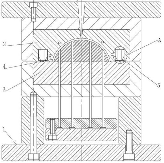
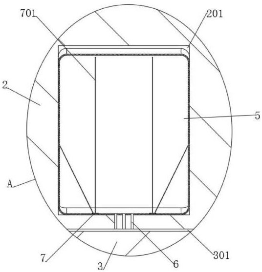
[0038] Please refer to Figure 1-10, including the lamp housing die-casting mold body 1, the temperature-varying exhaust cavity 2 and the air-groove core 3 matched with the temperature-varying exhaust cavity 2 are fixedly installed on the lamp housing die-casting mold body 1 , and the temperature variation
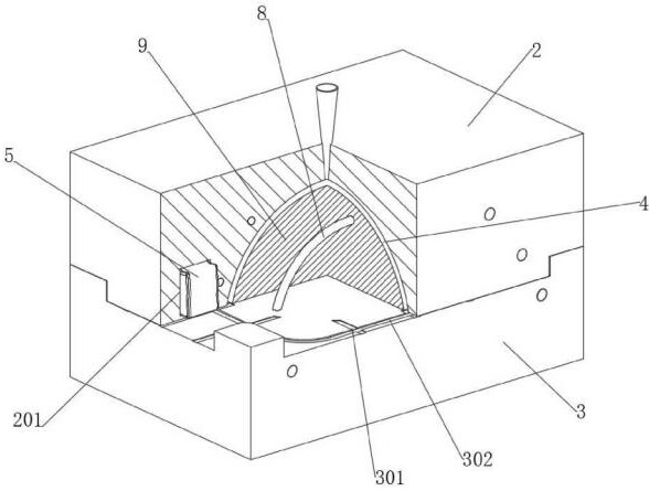
[0039] A die-casting gap 4 corresponding to the die-casting integrated lamp housing 11 is formed between the air cavity 2 and the air-groove core 3 , as shown in Fig. 3 . The connected branch sunken air groove 301, the upper end of the air groove type core 3 is provided with an annular flow equalizing air groove 302, and the annular flow equalizing air groove 302 is connected with the branch sunken air groove 301, and the annular flow equalizing air groove The depth of the 302 is the branch
[0040] 0.4-0.6 times the depth of the sunken air groove 301, through the annular flow equalizing air groove 302 to sink multiple branches
[0041] Type air tanks 301 are connected to...
Embodiment 2
[0087] Please refer to Figure 1-10, the upper end of the lamp housing die-casting mold body 1 is fixedly connected with a sprue bushing 101, and the lower end of the sprue bushing 101 extends to the inside of the temperature-varying exhaust cavity 2 and matches with the die-casting gap 4. Please refer to
[0088] See Figure 8, there are multiple direct-cooling cavities matching the die-casting gap 4 inside the temperature-varying exhaust cavity 2
[0089] The waterway 202, and the direct cooling cavity waterway 202 is located between the temperature-varying exhaust auxiliary chamber 201 and the die-casting gap 4. Please refer to Figure 8, the upper end of the air groove type core 3 is fixedly connected with the lamp housing core insert 9 by bolts, and a pair of arch bridge-shaped core waterways 8 are arranged in the air groove type core 3, and the arch bridge shape core waterways 8 and lamp housing
[0090]Core insert 9 fits. During die-casting, the molten aluminum alloy is...
PUM
 Abstract
Description
Claims
Application Information
 - R&D
- Intellectual Property
- Life Sciences
- Materials
- Tech Scout
- Unparalleled Data Quality
- Higher Quality Content
- 60% Fewer Hallucinations
Browse by: Latest US Patents, China's latest patents, Technical Efficacy Thesaurus, Application Domain, Technology Topic, Popular Technical Reports.
© 2025 PatSnap. All rights reserved.Legal|Privacy policy|Modern Slavery Act Transparency Statement|Sitemap|About US| Contact US: help@patsnap.com


