
Threaded hole machining device for large annular plane flange and stepped flange and method

A technology for flat flanges and processing devices, applied in positioning devices, tangent devices, metal processing equipment, etc., can solve the problem that it is difficult to ensure the verticality of the thread axis and the effective thread depth, and the thread processing of flange screw holes is time-consuming and laborious, and it is difficult to guarantee Work accuracy and other issues, to achieve the effect of compact structure, small appearance and easy operation

Pending Publication Date: 2021-08-13
渤海造船厂集团有限公司
View PDF5 Cites 0 Cited by
  • Summary
  • Abstract
  • Description
  • Claims
  • Application Information

AI Technical Summary

Problems solved by technology

[0002] In the process of ship construction, when the threaded holes of some large-scale ring-type flat flanges and stepped flanges are processed, due to the limited space, large-scale thread processing equipment cannot enter and fix them, and they are all processed manually. It is easy to cause the tap to break and remain in the blind hole, which is not easy to remove, and it is difficult to ensure the verticality of the thread axis and the effective thread depth. Especially for the processing of large-size coarse thread blind holes, it is even more difficult to ensure the accuracy of the work, resulting in flange screw hole thread The processing is time-consuming and laborious, and the construction efficiency is not high

Method used


Image

  • Threaded hole machining device for large annular plane flange and stepped flange and method
  • Threaded hole machining device for large annular plane flange and stepped flange and method
  • Threaded hole machining device for large annular plane flange and stepped flange and method

Examples


Embodiment Construction

[0017] The technical solutions in the embodiments of the present invention will be clearly and completely described below in conjunction with the accompanying drawings in the embodiments of the present invention. Obviously, the described embodiments are only part of the embodiments of the present invention, not all of them. Although the embodiments of the present invention have been shown and described, those skilled in the art can understand that various changes, modifications and substitutions can be made to these embodiments without departing from the principle and spirit of the present invention. and modifications, the scope of the invention is defined by the appended claims and their equivalents. Based on the embodiments of the present invention, all other embodiments obtained by persons of ordinary skill in the art without making creative efforts belong to the protection scope of the present invention.

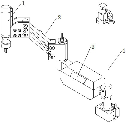
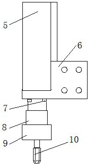
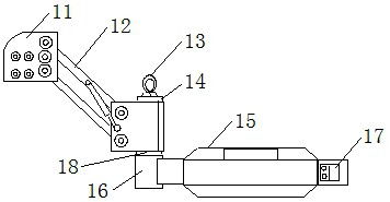
[0018] As shown in the figure, a large ring-type flat flange and st...


PUM


Abstract

The invention provides a threaded hole machining device for a large annular plane flange and stepped flange and a method. The machining device comprises a servo feeding driving mechanism, a rotary supporting arm assembly, a numerical control system and a magnetic positioning mechanism; a permanent magnet on the magnetic positioning mechanism is attracted to the surface of a workpiece, the position of the servo feeding driving mechanism is adjusted through the rotary supporting arm assembly to be aligned with a screw hole, a touch type human-computer interface of the numerical control system is used for operation, intelligent depth setting and automatic tapping and retreating are achieved, and the tapping requirement of any position within the rotating radius range of the rotary supporting arm assembly is met. The machining device is fixed to the surface of the workpiece or a temporary supporting plane through stable and strong attraction acting force provided by the permanent magnet, spatial movement of a screw tap is achieved through the rotary supporting arm assembly, the screw tap is driven to rotate through strong power provided by the servo feeding driving mechanism to achieve cutting, and threaded hole machining is controlled through the numerical control system in the period. The device and the method are applicable to machining of threaded holes of ships.

Description

technical field [0001] The invention relates to the technical field of mechanical processing at the shipbuilding site, in particular to a device and method for processing threaded holes of large-scale ring-type flat flanges and stepped flanges. Background technique [0002] In the process of ship construction, when the threaded holes of some large-scale ring-type flat flanges and stepped flanges are processed, due to the limited space, large-scale thread processing equipment cannot enter and fix them, and they are all processed manually. It is easy to cause the tap to break and remain in the blind hole, which is not easy to remove, and it is difficult to ensure the verticality of the thread axis and the effective thread depth. Especially for the processing of large-size coarse thread blind holes, it is even more difficult to ensure the accuracy of the work, resulting in flange screw hole thread The processing is time-consuming and laborious, and the construction efficiency i...

Claims


Application Information

Patent Timeline
IPC IPC(8): B23G1/18B23G1/44B23Q3/06
CPCB23G1/18B23G1/44B23Q3/06
Inventor 王波戚雪峰李拥李涛王娇锋邢伟马林
Owner 渤海造船厂集团有限公司
Learn More