
Storage battery electrode plate welding device

A welding device and electrode plate technology, applied in auxiliary devices, welding equipment, welding equipment, etc., can solve the problems of untreated smoke and dust, threatening the personal safety of workers, poor practicability, etc., to ensure physical health, protect the workshop environment, and automate good performance

Inactive Publication Date: 2021-08-13
江西京九电源科技有限公司
View PDF9 Cites 1 Cited by
  • Summary
  • Abstract
  • Description
  • Claims
  • Application Information

AI Technical Summary

Problems solved by technology

[0005] 1. The existing battery electrode plate welding device will generate a lot of smoke and dust during the welding process of the electrode plate. The welding device does not deal with the smoke and dust, and the smoke is directly discharged to pollute the working environment in the workshop and threaten the personal safety of the staff. The welding process of the welding device The automation performance is poor in the medium, requiring manual real-time control, which is not easy to use;
[0006] 2. The fixing mechanism of the welding device is a fixed structure design, which can only fix the battery electrode plate of a specified size, which leads to a small processing range of the welding device and poor practicability

Method used


Image

  • Storage battery electrode plate welding device
  • Storage battery electrode plate welding device
  • Storage battery electrode plate welding device

Examples


Embodiment 1

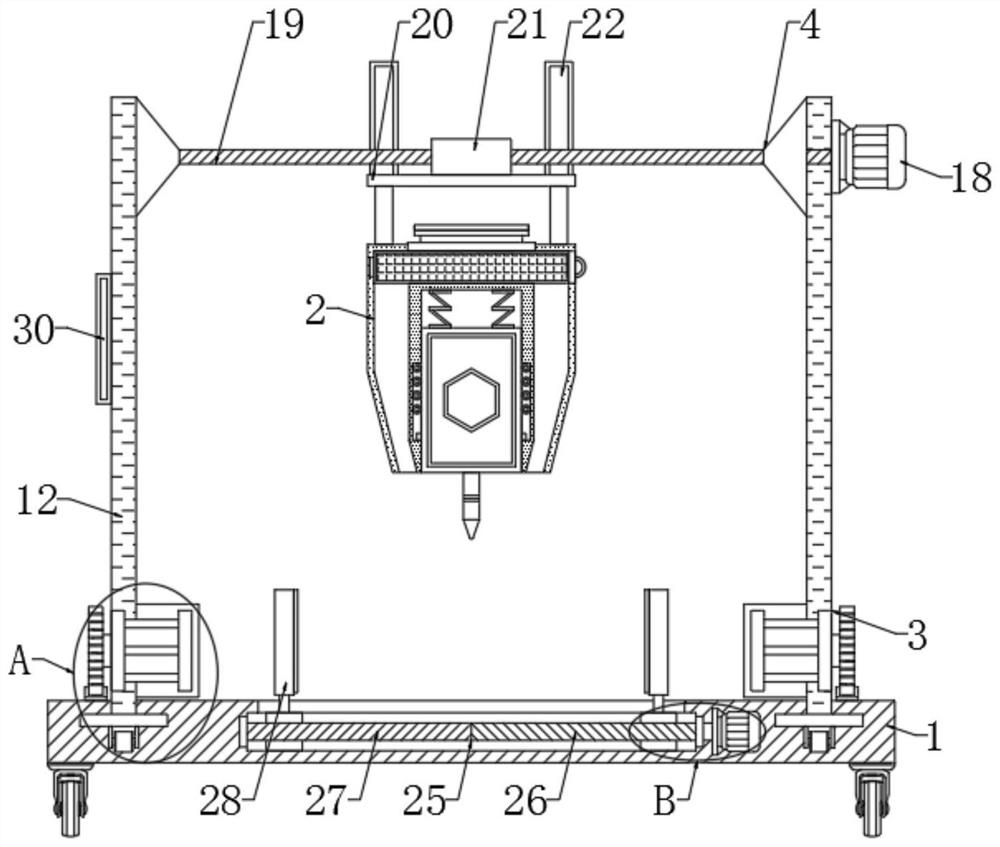
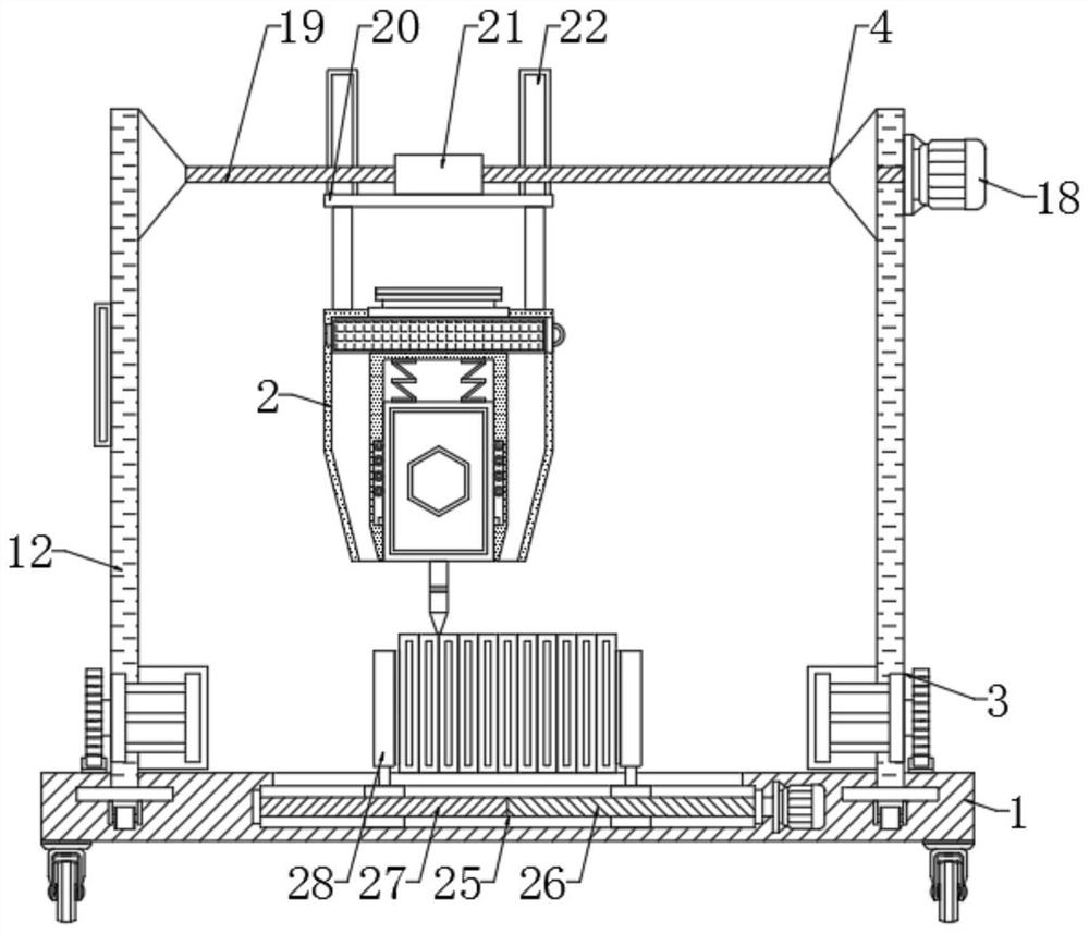
[0046] Embodiment 1: The battery electrode plate is placed on the top of the base 1, the electrode plate is fixed by the fixing mechanism 25, the first motor 13 drives the gear 14 to rotate, because the gear 14 meshes with the rack 15, the gear 14 rotates counterclockwise, and the support plate 12 drives the cigarette The mechanism 2 moves forward, the gear 14 rotates clockwise, the support plate 12 drives the smoking mechanism 2 to move backward, and then changes the Y-axis position of the smoking mechanism 2, the second motor 18 drives the screw rod 19 to rotate, because the screw sleeve 21 and the screw rod 19 Threaded connection, the screw rod 19 rotates clockwise, the base plate 20 drives the smoking mechanism 2 to move to the left, the screw rod 19 rotates counterclockwise, the base plate 20 drives the smoking mechanism 2 to move to the right, and the staff inputs the program to the control panel 30 to make the control panel 30 automatically control The welding device is ...

Embodiment 2

[0049] Embodiment 2: When the fixing mechanism 25 is in operation, the third motor 31 drives the first screw rod 26 and the second screw rod 27 to run simultaneously. Since the thread directions of the first screw rod 26 and the second screw rod 27 are opposite, the two sliders 29 drive The two splints 28 move to the top center of the base 1 synchronously. After the two splints 28 move and contact the electrode plate, the fixing is completed. The fixing mechanism of the welding device is a movable structure design, which can fix electrode plates of different sizes. The processing range wide.


PUM


Abstract

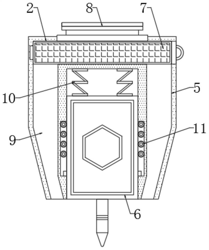
The invention provides a storage battery electrode plate welding device which comprises a base and a control panel. A smoke suction mechanism is arranged at the top of the base; the smoke suction mechanism comprises a shell and a welder; the welder is embedded in the bottom of the shell; a purification box is arranged at the top of an inner cavity of the shell; an exhaust fan is fixedly arranged at the center of the top of the shell; a smoke suction passage is formed in the inner wall of the shell; and the smoke suction passage is connected with the exhaust fan in a communicating mode. According to the invention, smoke generated by welding of the welder is directly sucked into the shell through the smoke suction passage, and after the smoke is purified by the purification box, the smoke is exhausted through the exhaust fan; compared with an existing welding device which is few in use function and inconvenient to use, the welding device has the smoke treatment function, effectively guarantees the body health of workers and protects the workshop environment; and the welding device can move in multiple axial directions, and the automation performance is good.

Description

technical field [0001] The invention relates to the technical field of battery processing, in particular to a battery electrode plate welding device. Background technique [0002] A battery is a device that directly converts chemical energy into electrical energy. It is a rechargeable battery designed to be recharged through a reversible chemical reaction. It usually refers to a lead-acid battery, which is a type of battery and belongs to the secondary battery. Battery, its working principle is to use external electric energy to regenerate internal active materials when charging, store electric energy as chemical energy, and convert chemical energy into electric energy output again when it needs to be discharged, such as mobile phone batteries commonly used in life; [0003] When the battery is being discharged, the metal lead is the negative electrode, which undergoes an oxidation reaction to generate lead sulfate, and the lead dioxide is the positive electrode, which under...

Claims


Application Information

Patent Timeline
IPC IPC(8): B23K31/02B23K37/00
CPCB23K31/02B23K37/00
Inventor 吴明耀刘三元
Owner 江西京九电源科技有限公司
Learn More