Grinding equipment with strength convenient to adjust for building material processing
A convenient and powerful technology, used in metal processing equipment, grinding/polishing equipment, machine tools suitable for grinding workpiece planes, etc., can solve problems such as reduced grinding efficiency, frequent replacement of grinding discs, and equipment difficult to grind at different depths. Achieve the effect of improving grinding efficiency, improving grinding quality, and increasing the scope of application
- Summary
- Abstract
- Description
- Claims
- Application Information
AI Technical Summary
Problems solved by technology
Method used
Image
Examples
Embodiment 1
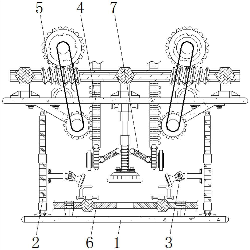
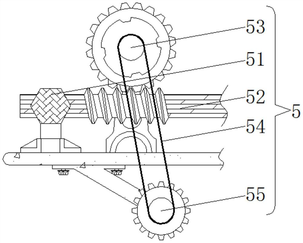
[0026] see figure 1 , figure 2 , a kind of grinding equipment for convenient adjustment of strength for processing building materials, including a bottom plate 1, a hydraulic rod 2 is welded on the top of the bottom plate 1, a vacuum cleaner 3 is arranged on the side of the hydraulic rod 2, a top plate 4 is welded on the top of the hydraulic rod 2, and a hydraulic rod 2 There are two sets, which are distributed symmetrically around the midpoint of the bottom plate 1, and are welded to the left and right ends of the bottom plate 1 in a vertical state; there are two vacuum cleaners 3, which are respectively set on the inner sides of the two left and right hydraulic rods 2;
[0027] The top plate 4 and the bottom plate 1 are in a parallel state, and two hydraulic rods 2 are welded between the top plate 4 and the bottom plate 1; A threaded sleeve 52, the top of the threaded sleeve 52 is meshed with a driving tooth 53, the outer periphery of the driving tooth 53 is sleeved with a...
Embodiment 2
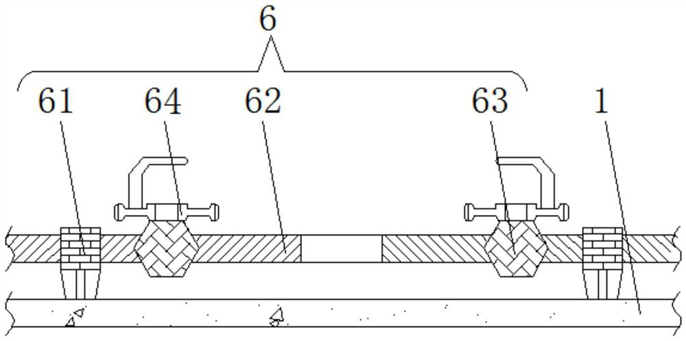
[0030] see figure 1 , image 3 , a kind of grinding equipment for building material processing with convenient adjustment of strength, including a base plate 1, characterized in that: the top of the base plate 1 is welded with a hydraulic rod 2, the side of the hydraulic rod 2 is provided with a vacuum cleaner 3, and the top of the hydraulic rod 2 is welded with a top plate 4 , there are two hydraulic rods 2, which are distributed symmetrically around the midpoint of the base plate 1, and welded to the left and right ends of the base plate 1 in a vertical state; there are two vacuum cleaners 3, which are respectively arranged on the left and right hydraulic rods 2 inside of
[0031] The top plate 4 and the bottom plate 1 are parallel, and the top plate 4 and the bottom plate 1 are welded by two hydraulic rods 2; the top of the top plate 4 is provided with a driving mechanism 5, and the top of the bottom plate 1 is provided with a clamping mechanism 6, which Including the lim...
Embodiment 3
[0034] see figure 1 , Figure 4 , a kind of grinding equipment for building material processing with convenient adjustment of strength, including a base plate 1, characterized in that: the top of the base plate 1 is welded with a hydraulic rod 2, the side of the hydraulic rod 2 is provided with a vacuum cleaner 3, and the top of the hydraulic rod 2 is welded with a top plate 4 , there are two hydraulic rods 2, which are distributed symmetrically around the midpoint of the base plate 1, and welded to the left and right ends of the base plate 1 in a vertical state; there are two vacuum cleaners 3, which are respectively arranged on the left and right hydraulic rods 2 inside of
[0035] The top plate 4 is parallel to the bottom plate 1, and two hydraulic rods 2 are welded between the top plate 4 and the bottom plate 1; Grinding mechanism 7 is provided; Grinding mechanism 7 comprises pressure rod 71, and the bottom of pressure rod 71 is rotatably connected with grinding wheel 1 ...
PUM
 Abstract
Description
Claims
Application Information
 - R&D
- Intellectual Property
- Life Sciences
- Materials
- Tech Scout
- Unparalleled Data Quality
- Higher Quality Content
- 60% Fewer Hallucinations
Browse by: Latest US Patents, China's latest patents, Technical Efficacy Thesaurus, Application Domain, Technology Topic, Popular Technical Reports.
© 2025 PatSnap. All rights reserved.Legal|Privacy policy|Modern Slavery Act Transparency Statement|Sitemap|About US| Contact US: help@patsnap.com


