Multi-path multi-control vacuum-pumping system equipment and vacuum-pumping method

A vacuum system and vacuum technology, applied in vacuum evaporation plating, ion implantation plating, gaseous chemical plating, etc., can solve the problems of uneven thickness of coating film and uneven distribution of plasma, and achieve uniform thickness The effect of improving the uniformity of distribution

Active Publication Date: 2021-08-13
BETONE TECH SHANGHAI
View PDF5 Cites 0 Cited by
  • Summary
  • Abstract
  • Description
  • Claims
  • Application Information

AI Technical Summary

Problems solved by technology

[0003] In view of the above-mentioned shortcomings of the prior art, the purpose of the present invention is to provide a multi-channel multi-control vacuum pumping system equipment and a vacuum pumping method, which are used to solve the problem of residual gas or plasma in the coating cavity easily caused by the existing vacuum pumping methods. Uneven distribution, leading to the problem of uneven film thickness deposited by vapor deposition

Method used


Image

  • Multi-path multi-control vacuum-pumping system equipment and vacuum-pumping method
  • Multi-path multi-control vacuum-pumping system equipment and vacuum-pumping method
  • Multi-path multi-control vacuum-pumping system equipment and vacuum-pumping method

Examples


Embodiment 1

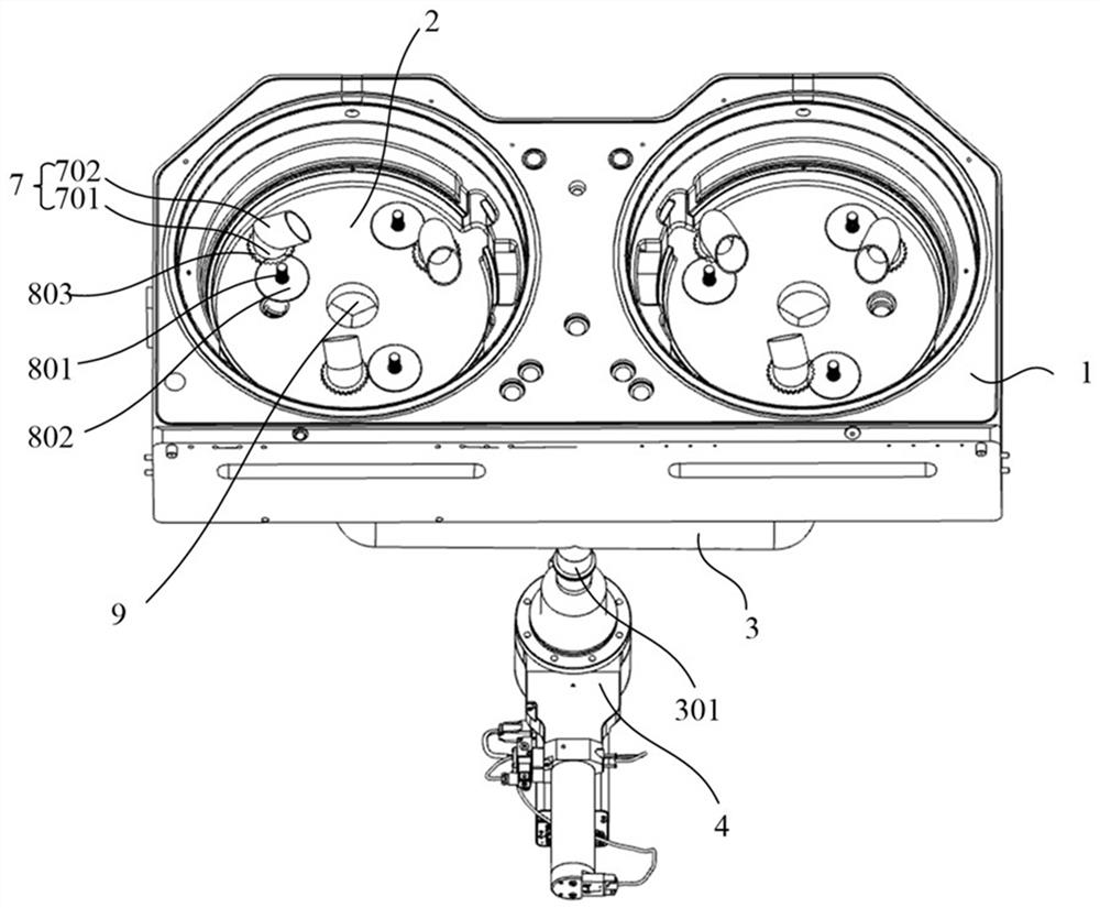
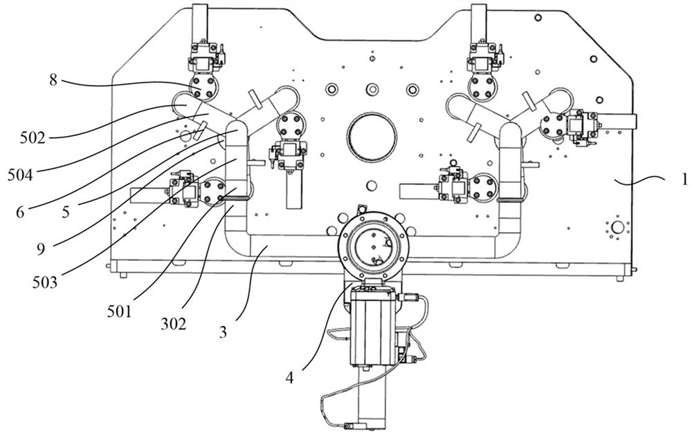
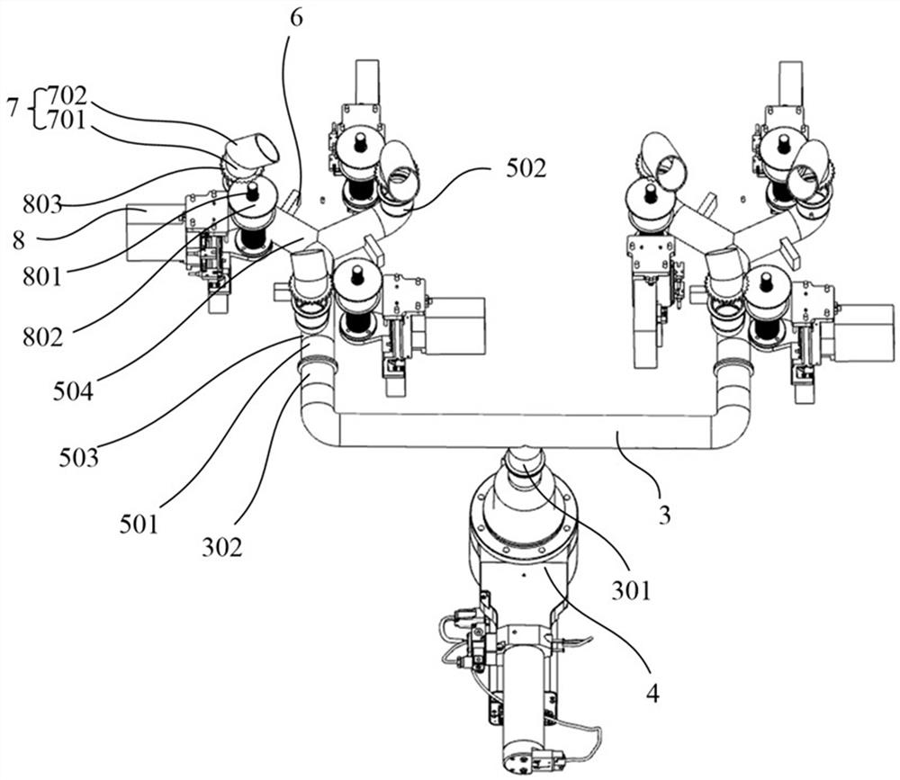
[0044] In this embodiment, a multi-channel and multi-control vacuum pumping system equipment is provided, please refer to figure 1 and figure 2 , respectively showing the top view and bottom view of the multi-channel multi-control vacuum system equipment, including a body 1, a plurality of chambers 2, a main pipeline 3, a vacuum device 4, a plurality of sub-pipes 5, and a plurality of control valves 6 , a plurality of universal suction heads 7 and a plurality of driving mechanisms 8, wherein a plurality of the chambers 2 are arranged in the body 1 at intervals; the main pipeline 3 includes a main joint 301 and a plurality of taps 302 The vacuum device 4 is connected to the main joint 301; a plurality of the sub-pipes 5 are respectively connected to different sub-pipes 302 and different chambers 2, and the sub-pipes 5 include a first joint 501 and at least one second joint 502, the first joint 501 is connected to the tap 302, the second joint 502 is connected to the bottom of...

Embodiment 2

[0062] This embodiment provides a vacuum pumping method, which adjusts the pumping speed and the pumping direction of the universal pumping head in the chamber during the vacuum pumping process. It should be pointed out that this method can be implemented by using the multi-channel multi-control vacuum system equipment described in Embodiment 1 or other suitable equipment.

[0063] As an example, in order to achieve uniformity control more accurately, a plurality of the universal suction heads are provided in the chamber, and the suction speed and the suction direction of the multiple universal suction heads are respectively adjusted to achieve the desired The uniformity of gas or plasma distribution in each area of ​​the chamber.

[0064] As an example, the air pressure in different regions in the chamber can be detected during the vacuuming process, and the suction speed and direction of the universal suction head can be adjusted according to the unevenness of the air pressu...


PUM


Abstract

The invention provides multi-path multi-control vacuum-pumping system equipment and a vacuum-pumping method. The equipment comprises a body, a plurality of cavities, a main pipeline, a vacuum-pumping device, a plurality of branch pipelines, a plurality of control valves, a plurality of universal air exhaust heads and a plurality of driving mechanisms, wherein the plurality of driving mechanisms are connected to the different universal air exhaust heads correspondingly so as to change air exhaust directions of the universal air exhaust heads, at least one corresponding universal air exhaust head can be arranged in one of the cavities, and each universal air exhaust head can be controlled separately. According to the vacuum-pumping method, air exhaust speeds and the air exhaust directions of the universal air exhaust heads in the cavities can be adjusted according to non-uniformity of gas in the cavities or non-uniformity of a deposited film in a vacuum-pumping process, so that distribution uniformity of residual gas in the cavities or distribution uniformity of plasma in the cavities during a coating process reaction is improved, and finally, thickness uniformity of a coating layer is improved; and the heights and/or directions of the universal air exhaust heads can be manually adjusted in advance, and the air exhaust speeds and directions of the universal air exhaust heads can be adjusted in real time in the vacuum-pumping process.

Description

technical field [0001] The invention belongs to the field of semiconductor high-end manufacturing equipment, and in particular relates to a multi-channel multi-control vacuum pumping system device and a vacuum pumping method. Background technique [0002] Today's thin film manufacturing process must use vacuum equipment whether it uses CVD (Chemical Vapor Deposition) or PVD (Physical Vapor Deposition). In the general semiconductor or thin film process, it must be carried out in a relatively high vacuum environment, and it is usually necessary to make the vacuum in the deposition chamber reach a certain level (about 10 -5 torr), the subsequent thin film deposition process can continue. During the coating process, it is necessary to continuously vacuumize, coat, vacuumize, and coat again. The purpose is to extract the remaining exhaust gas or plasma from the previous coating reaction to prevent the impact on the next coating. If If the exhaust gas or residual plasma is not ...

Claims


Application Information

Patent Timeline
Patent Type & Authority Applications(China)
IPC IPC(8): C23C16/44C23C16/455C23C14/56
CPCC23C14/56C23C16/4412C23C16/455
Inventor 封拥军周东平崔世甲宋维聪
Owner BETONE TECH SHANGHAI
Why Eureka
Try Eureka