Pulse laser spectrum time sequence synthesis system and method

A technology of pulsed laser and synthesis method, applied in the field of laser, can solve the problems of complex transmission device, and achieve the effect of high beam quality, simple, efficient and compact structure and good stability.

Active Publication Date: 2021-08-13
武汉光谷航天三江激光产业技术研究院有限公司
View PDF8 Cites 3 Cited by
  • Summary
  • Abstract
  • Description
  • Claims
  • Application Information

AI Technical Summary

Problems solved by technology

This method uses the principle of polarization

Method used


Image

  • Pulse laser spectrum time sequence synthesis system and method
  • Pulse laser spectrum time sequence synthesis system and method
  • Pulse laser spectrum time sequence synthesis system and method

Examples


Example Embodiment

[0050] The present invention also provides a pulsed laser spectral timing synthesis method, including the following steps:

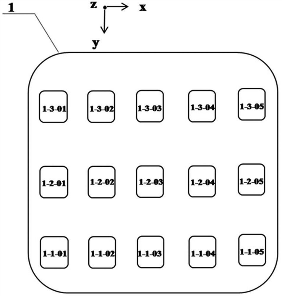
[0051] (1) The array sorting of the pulsed laser source of different wavelengths is performed, forming a two-dimensional array of square light sources in a multi-set horizontal direction light source group and vertical direction.

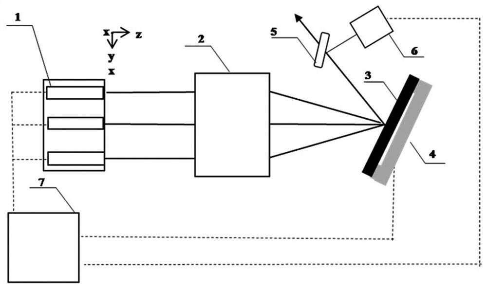
[0052] (2) Controlling the synchronous pulse laser in the horizontal direction of the light source, simultaneously collecting the pulsed laser, so that the pulse laser is incident on the grating 3 at the specified angular interval, and select an incident pulse according to the first level diffraction conditions of the diffraction equation. The wavelength of the laser is different, so that the angle of incidence of the single pulse laser in the horizontal direction is different, while the diffraction angle is the same, in this manner, the single pulse laser of each group of horizontal direction light source groups is based on the s...

Example Embodiment

[0059] Example 1

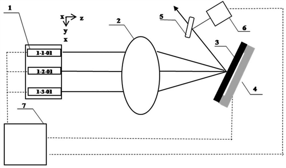
[0060] like figure 2 and image 3 As shown in the horizontal direction, in the first group as an example, a plurality of different wavelengths of pulsed laser sources 1-1-01, 1-1-02, 1-1-03, 1-1-04, 1-1 -05, the position interval is 10mm, one-dimensional arrangement constitutes a set, the light source beam is located on one side of the collimated focusing device 2, located on the same straight line and each other, total 3 group; in the vertical direction, in the vertical direction As an example, the pulse light source 1-1-01, 1-2-01, 1-3-01 is arranged in the same line, and the position interval is 40mm, and each other is parallel, a total of 5 columns. Also located on one side of the collimal focusing device 2, the collimated focusing device is a lens having a focal length of 1.06m:

[0061] The first set of pulse lasers 1-1-01, 1-1-02, 1-1-03, 1-1-04, 1-1-05 has a meula energy of about 10mJ, and the pulse width is 10ms, the beam quality Near diffraction limit, ...


PUM


Abstract

The invention belongs to the technical field of laser, and particularly discloses a pulse laser spectrum time sequence synthesis system and method. The system comprises a pulse laser light source two-dimensional array, a collimating and focusing device, a grating, a fast reflecting mirror and a control device. The method comprises the following steps: periodically transmitting pulse laser, separating the collimated pulse laser, and selecting the wavelength of the pulse laser incident by the grating so as to allow the incident angles of the single pulse laser of horizontal light source groups to be different while diffraction angles to be the same; subjecting the single pulse laser of each horizontal light source group to primary diffraction output according to the same diffraction angle so as to realize spectrum synthesis of the pulse laser of the horizontal light source groups; and adjusting the light beam pointing of the horizontal light source groups so as to allow the light beam pointing of each horizontal light source group to the same as the light beam pointing of the first horizontal light source group, thereby realizing time sequence synthesis of pulse light sources in a vertical direction. According to the invention, the laser power/energy is improved while high beam quality is maintained.

Description

Technical field [0001] The present invention belongs to the field of laser technology, and more particularly to a pulsed laser spectral timing synthesis system and method. Background technique [0002] With the development of technology development and economic growth, in the field of industrial manufacturing, the brightness of the laser system is increasingly requested. In many areas, the power energy brightness of the laser is no longer able to meet the application needs. Laser power energy improves the heat-conducting effect, nonlinear effect, etc., and often brings deterioration of beam quality during power promotion. Synthesis of multi-channel beams is an important way to improve laser brightness and power; a multi-channel pulse laser, by controlling the light light of the laser, achieves different timing pulsed lasers through mechanical methods, and a common aperture output on space is combined. All the way, the power / energy extension can also be achieved, and the quality...

Claims


Application Information

Patent Timeline
IPC IPC(8): H01S3/00G02B27/10
CPCG02B27/1006G02B27/1086H01S3/005H01S3/0071
Inventor 赵朋飞王旭徐旭光梁传样韩西萌李强武春风姜永亮胡金萌吕亮
Owner 武汉光谷航天三江激光产业技术研究院有限公司
Why Eureka
Try Eureka