
A vertical cavity surface emitting laser and its manufacturing method and application

A technology of vertical cavity surface emission and manufacturing method, applied in the field of vertical cavity surface emitting lasers, can solve problems such as uneven spatial distribution, and achieve the effect of simple structure

Active Publication Date: 2021-09-28
VERTILITE CO LTD
View PDF5 Cites 0 Cited by
  • Summary
  • Abstract
  • Description
  • Claims
  • Application Information

AI Technical Summary

Problems solved by technology

[0003] At present, the light spots emitted by vertical cavity surface emitting lasers usually have uneven spatial distribution (far field). This uneven light spot cannot directly apply vertical cavity surface emitting lasers to TOF measurement, security camera and other technologies

Method used


Image

  • A vertical cavity surface emitting laser and its manufacturing method and application
  • A vertical cavity surface emitting laser and its manufacturing method and application
  • A vertical cavity surface emitting laser and its manufacturing method and application

Examples


Embodiment Construction

[0051] The embodiments of the present invention will be easily understood by those skilled in the

[0052] It should be noted that the illustrations provided in the present embodiment will illustrate the basic contemplation of the present invention in a schematic manner, and only the components, shapes, shapes, shapes, shapes related to the components of the present invention are displayed in the pattern rather than in accordance with the actual implementation. Dimensions, the type, quantity, and proportion of each component can be a random change in the actual implementation, and its component layout is also more complicated.

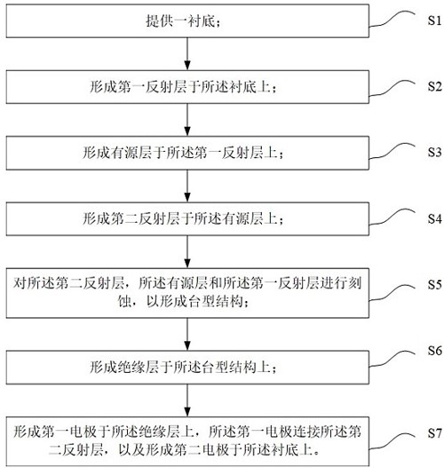
[0053] like figure 1 As shown, the present embodiment propo...


PUM

PropertyMeasurementUnit
thicknessaaaaaaaaaa

Abstract

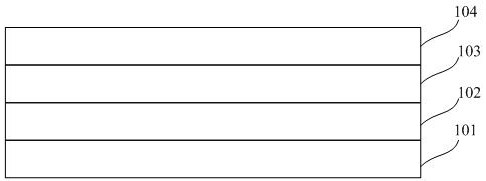
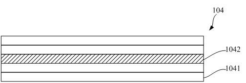
The present invention proposes a vertical cavity surface emitting laser and its manufacturing method and application, comprising: a substrate; a first reflective layer disposed on the substrate; an active layer disposed on the first reflective layer, with emitting laser beams; the second reflective layer is disposed on the active layer; wherein, the second reflective layer includes at least one optical scattering layer, and the laser beam passes through the optical scattering layer to form a far-field spot, The optical scattering layer scatters the laser beam at the edge into the central area of ​​the far-field spot; wherein, the optical scattering layer includes optical scattering particles, and the optical scattering particles include an undulating interface; wherein, the The roughness of the optical scattering layer is greater than the roughness of the first reflective layer. The vertical cavity surface emitting laser proposed by the present invention can obtain far-field light spots with uniform energy distribution.

Description

Technical field [0001] The present invention relates to the field of laser light, and more particularly to a vertical cavity surface emission laser and a manufacturing method thereof. Background technique [0002] Vertical Cavity Surface Emitting Laser, VCSEL is based on a gallium arsenide semiconductor material, and other light sources such as LED (LED) and LD (Laser Diode, Laser Diode) are different. The circular output spot, the single-length die output, the threshold current is small, the price is low, and it is easy to become advantages such as large area arrays, widely used in optical communication, optical interconnect, optical storage and other fields. [0003] At present, the spot, spatial distribution (far field) of the vertical cavity emitting laser is not uniform, which cannot be directly applied to the vertical cavity emitting laser directly in TOF measurement, safety imaging. Inventive content [0004] In view of the above prior art defects, the present invention p...

Claims


Application Information

Patent Timeline
Patent Type & Authority Patents(China)
IPC IPC(8): H01S5/183
CPCH01S5/18361
Inventor 李辉杰李含轩李善文
Owner VERTILITE CO LTD
Learn More