A low-stress boost inverter and its implementation method

An implementation method and inverter technology, applied in the direction of converting AC power input to DC power output, output power conversion device, electrical components, etc., can solve the problems of unbalanced capacitor voltage, lower output power, and using more devices. Achieve the effects of reducing harmonic distortion rate, increasing output level, and eliminating specific harmonics

Active Publication Date: 2022-05-10
ZHENGZHOU UNIV
View PDF6 Cites 0 Cited by
  • Summary
  • Abstract
  • Description
  • Claims
  • Application Information

AI Technical Summary

Problems solved by technology

Traditional multilevel inverters are divided into three types of typical structures, namely, diode clamped type, flying capacitor type and cascaded H bridge type, among which diode clamped type and flying capacitor type multilevel inverters need to use more Many diodes or capacitors are used to clamp the neutral point, the structure is complex, and many devices are used; in addition, the above two multi-level inverters also have the problem of unbalanced capacitor voltage; the cascaded H-bridge multi-level inverter devices require the use of a large number of isolated voltage sources
[0004] The traditional multi-level inverters mentioned above are mostly step-down inverters. In applications that require a boost, such as in the field of distributed photovoltaic power generation, the photovoltaic array of the photovoltaic power generation device is usually a DC low-voltage source, and its output voltage gain is usually Unable to meet grid-connected conditions or fail to reach the rated voltage of electrical equipment
Therefore, it is necessary to add DC-DC and AC-AC boost converters at the front end and output rear end of the inverter respectively. The bulky iron core and multi-winding coils of the transformer will make the system structure complex, reduce the output power, and increase the power consumption. area of ​​land

Method used


Image

  • A low-stress boost inverter and its implementation method
  • A low-stress boost inverter and its implementation method
  • A low-stress boost inverter and its implementation method

Examples


Embodiment 1

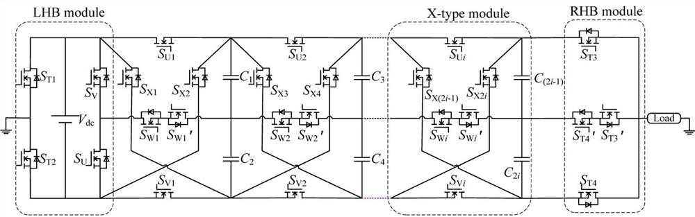
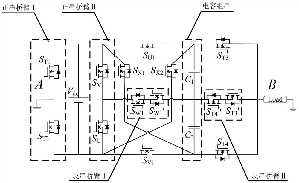
[0048] as attached figure 2 As shown, a setting where the DC power supply V dc A low-stress boost inverter between the load and the load, which includes a left half-bridge module, an X-type bipolar module and a right half-bridge module, and the left half-bridge module includes positive series bridge arm I and positive series bridge arm II, so The X-type bipolar module includes reverse-series bridge arm I, X-type bridge arm and capacitor string, and the right half-bridge module includes reverse-series bridge arm II and forward-series bridge arm III;

[0049] One end of the reverse series bridge arm I is connected to the midpoint of the forward series bridge arm II, and the other end of the reverse series bridge arm I is connected to the midpoint of the capacitor string and one end of the reverse series bridge arm II. The other end of the reverse series bridge arm II is connected to the midpoint of the forward series bridge arm III;

[0050] The midpoint of the positive serie...

Embodiment 2

[0062] On the basis of the low-stress boost inverter with one X-type bipolar module in Embodiment 1, this embodiment provides a specific implementation method of a low-stress boost inverter:

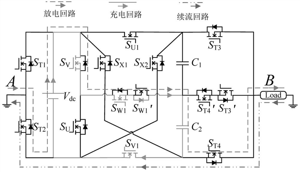
[0063] The low-stress boost inverter outputs 7 levels in one working cycle, including the switching of seven working modes:

[0064] Working mode I, setting: the switching tube S of the positive series bridge arm I T2 , the switching tube S of the positive series bridge arm II V , the switching tube S of the X-shaped bridge arm V1 , the switching tube S of the anti-series bridge arm I W1 , the switching tube S of the positive series bridge arm III T4 and the switching tube S of the anti-series bridge arm II T3 'Turn on, the rest of the switch tubes are turned off, and the output level is 0;

[0065] as attached image 3 As shown, the electrolytic capacitor C of the capacitor string 2 with DC supply V dc charged in parallel to V dc , electrolytic capacitor C 1 constant;

[0066...

Embodiment 3

[0102] This embodiment provides a low-stress step-up inverter system, including an inverter and a controller, and the inverter is the above-mentioned low-stress step-up inverter.

[0103] This embodiment also provides another specific implementation of a low-stress boost inverter system, including an inverter and a controller. Steps of a method for realizing a voltage inverter.

[0104] This embodiment provides a specific implementation manner of a readable storage medium, on which instructions are stored, and when the instructions are executed by a processor, the steps of the method for implementing a low-stress boost inverter as described above are implemented.


PUM


Abstract

The present invention provides a low-stress boost inverter and its implementation method. The low-stress boost inverter includes a left half-bridge module, an X-type bipolar module and a right half-bridge module. The left half-bridge module Including forward series bridge arm I and forward series bridge arm II, the X-type bipolar module includes reverse series bridge arm I, X-type bridge arm and capacitor string, and the right half bridge module includes reverse series bridge arm II and forward series bridge arm III ; One end of the anti-series bridge arm I is connected to the midpoint of the forward series bridge arm II, the other end of the anti-series bridge arm I is connected to the midpoint of the capacitor string and one end of the anti-series bridge arm II, and the other end of the anti-series bridge arm II is connected to the forward series bridge The midpoint of arm III; the midpoint of the positive series bridge arm I and the midpoint of the positive series bridge arm III are used as the AC voltage output end of the low-stress boost inverter; by expanding the X-type bipolar module, the boost gain and The number of output levels, but the maximum reverse voltage stress of the switch remains unchanged.

Description

technical field [0001] The invention relates to the technical field of inverters, in particular to a low-stress boost inverter and its realization method. Background technique [0002] With the global energy crisis and the awakening of environmental awareness, it has become a common consensus in human society to build an energy supply system dominated by renewable clean energy. Solar energy has the characteristics of ease of use, universality and cleanness, and has become the best alternative to fossil energy, and the photovoltaic power generation industry has therefore developed rapidly. In the photovoltaic power generation system, the photovoltaic inverter plays a vital role, and its performance affects the stability of the entire power supply system. [0003] Multilevel inverters have the advantages of being able to output approximately sinusoidal ladder waveforms, reduce voltage total harmonic distortion, reduce peak reverse voltage of devices, smaller du / dt values, and...

Claims


Application Information

Patent Timeline
Patent Type & Authority Patents(China)
IPC IPC(8): H02M7/5387H02M1/088H02M1/12H02M1/32
CPCH02M7/53871H02M1/088H02M1/12H02M1/32
Inventor 王要强王昌龙郭彦勋章健王克文梁军
Owner ZHENGZHOU UNIV
Why Eureka
Try Eureka