Annular hollow part additive manufacturing smoke-discharging and dust-removing device and method

A technology of additive manufacturing and dust removal device, which is applied in the field of additive manufacturing, can solve the problems of exhaust air velocity attenuation, lower forming quality, and damage to the powder bed surface, etc., to reduce the air flow area, avoid damage, and improve molding quality. Effect

Pending Publication Date: 2021-08-17
XI AN JIAOTONG UNIV
View PDF4 Cites 0 Cited by
  • Summary
  • Abstract
  • Description
  • Claims
  • Application Information

AI Technical Summary

Problems solved by technology

However, the technique does not work well on powder beds applied to larger formats
The speed of the exhaust air flow is severely attenuated, and it is difficult to take away the dust particles. Although the flow velocity at the exhaust port can be maintained by increasing the flow velocity of the initial airflow—that is, the flow velocity at the blower outlet of the blowing device, but too high The wind speed may blow away the powder particles near the air blowing device, destroying the surface of the powder bed and reducing the forming quality

Method used


Image

  • Annular hollow part additive manufacturing smoke-discharging and dust-removing device and method
  • Annular hollow part additive manufacturing smoke-discharging and dust-removing device and method
  • Annular hollow part additive manufacturing smoke-discharging and dust-removing device and method

Examples


Embodiment 1

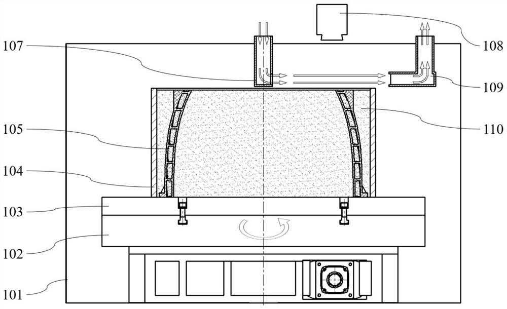
[0040] like figure 1 As shown, in the sealed forming chamber 101, a rotary table 102 is provided, and a substrate 103 is provided on the rotating table 102, and the substrate 103 is fastened to the rotary table 102. The substrate 103 is provided with a cylinder body 104 fixed to the substrate 103, and the outer cylinder 104 is formed in the forming workpiece 105. The area where the outer cylinder 104 is surrounded, that is, the molding region of the workpiece, in the forming region, and is laid in the process requirements.

[0041] For large formats of powder beds, the scanning area of ​​a scanning system is generally not sufficient to cover the entire shaped area. However, if the scanning area of ​​the scanning system has a contour diameter larger than the contour radius of the entire forming area, the scanning system 108 can be disposed at 1 / 2 of the outer cylinder body 104 contour radius. like figure 1 Indicated. Thus, when the rotating table 102 drives the substrate 103, the o...

Embodiment 2

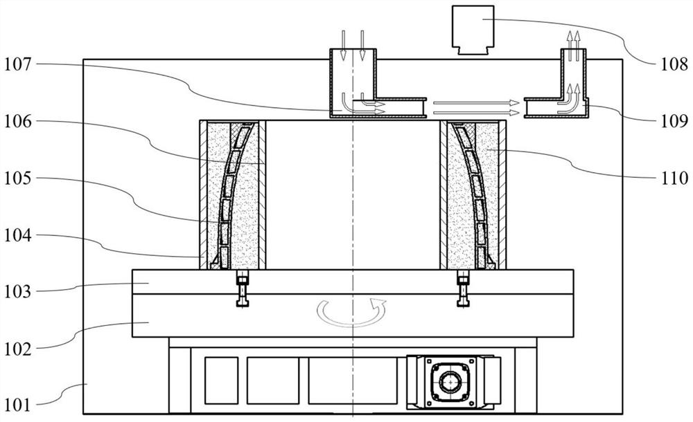
[0045] For barrel thin-walled parts, its overall contour is large, but its wall thickness is relatively thin, and there is no entity in which the center / internal position is not. Typical parts such as rocket hoses, vortex engine housings, rocket engines tail nozzle. Because these parts often have complex flow path structures inside the housing, such a large thin-walled complex member is produced using a powder bed molten forming process, the production cycle can be greatly shortened than the traditional manufacturing process.

[0046] like figure 2 As shown, an inner cylinder body 106 is provided in the outer cylinder 104, the forming workpiece 105, and the metal powder 110 are in the outer cylinder 104 and the inner cylinder body 106. Both the air opening of the blowing device 107 and the exhaust port of the exhaust device 109 are provided with a guide cover, and the two air-blown spacings are greater than the wall thickness of the shaped member, and the spacing of the blowing ...

Embodiment 3

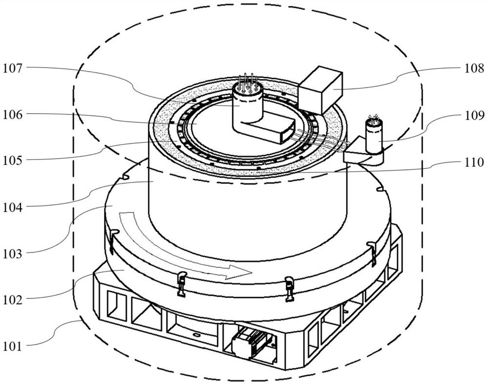
[0048] When the shape is large, the use of a multi-set scan system can significantly increase the forming efficiency of the workpiece. The larger forming formation also provides the necessary installation space for the arrangement of the multi-set scanning system.

[0049] like Figure 4 As shown, the blowing device 107 has four blowing ports evenly distributed on the circumference. Accordingly, in four corresponding directions, four sets of scanning systems and four sets of exhaust devices are provided. During the molding process, the blowing device 107, the exhaust device (109) and the scanning system are relatively positioned, and the molded member is rotationally formed, and the molded heat can be concentrated to prevent flue gas.


PUM


Abstract

The invention discloses an annular hollow part additive manufacturing smoke-discharging and dust-removing device and method. An air blowing device is arranged at the upper end of a forming chamber; an exhaust device is arranged on the side wall of the forming chamber; a connecting line between an air outlet of the air blowing device and an air inlet of the exhaust device is horizontally arranged and located at the upper end of a forming surface; the air blowing device is communicated with an air blowing source or an exhaust port is connected with an exhaust source; the air outlet of the air blowing device and the air inlet of the exhaust device are formed in the two sides of a forming area; an exhaust laminar flow is formed on the forming surface of an annular hollow part; and smoke is blown to the exhaust port through the exhaust device and the air blowing device to be directly exhausted. According to the invention, spreading of smoke generated in the energy beam melting process can be effectively avoided; the exhaust device and the air blowing device are arranged on the two sides of the forming area in the same plane; an airflow flowing area can be reduced; air of an air outlet device can effectively maintain the flow speed at the exhaust port; and damage to the surface of a powder bed can be effectively avoided at the relatively low air speed; and the forming quality is improved.

Description

Technical field [0001] The present invention belongs to the technical field of additive manufacturing, and is specifically involved in an annular hollow component additive manufacturing exhaust dust removing device and method. Background technique [0002] Pink bed molten forming technique (PBF), is a selective scan with energy bundle (such as laser or electron beam, etc.) in a pre-paid powder bed, and the metal powder in the selection is merged, and the cumulative substrate Mechanical performance complicated metal parts comparable to forges will be manufactured. [0003] However, the metal powder material produces soot during the melting of the energy bundle. These soot will reduce the power of the energy bundle, which will affect the purity of the powder, thereby reducing the molding quality of the workpiece; if the smoke adheres to the guide rail, the screw and other motion systems, it will affect the formation accuracy of the workpiece, reducing the service life of the equipm...

Claims


Application Information

Patent Timeline
IPC IPC(8): B22F10/77B22F12/00B22F10/28B33Y40/00
CPCB33Y40/00
Inventor 陈祯韦继翀张树哲邹亚桐卢秉恒姚森
Owner XI AN JIAOTONG UNIV
Why Eureka
Try Eureka