Clean plate automatic conveying, flipping and capping device

A technology of automatic conveying and flipping covers, which is applied in the direction of cleaning devices, transportation and packaging, conveyor objects, etc., can solve the problems of staff fatigue, increased labor intensity, and low production efficiency, so as to reduce labor intensity, save manpower, and improve efficiency effect

Active Publication Date: 2022-08-09
山东晶承净化科技有限公司
View PDF7 Cites 0 Cited by
  • Summary
  • Abstract
  • Description
  • Claims
  • Application Information

AI Technical Summary

Problems solved by technology

[0003] The purpose of the present invention is to provide a clean plate automatic conveying flipping and closing device, which solves the problem that two people need to grab one side to flip and close the clean plate at present, which not only consumes manpower but also increases labor intensity, and takes a long time for the staff It will be very tiring, and the production efficiency is relatively low, so there is a need for an automatic flipping and closing equipment

Method used


Image

  • Clean plate automatic conveying, flipping and capping device
  • Clean plate automatic conveying, flipping and capping device
  • Clean plate automatic conveying, flipping and capping device

Examples


Embodiment 1

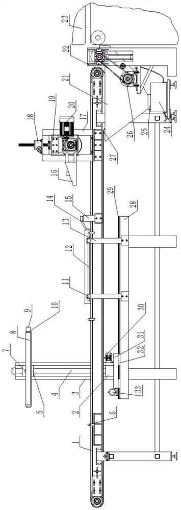
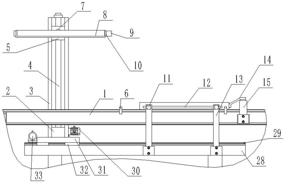
[0034] Example 1, as figure 1 , 2 , 5 and Image 6 As shown in the figure, the present invention is an automatic conveying, flipping and capping device for clean boards, including a conveyor 1 arranged at the left end of the pressing device, and a horizontal guide rail frame 28 is provided at the front and rear sides of the left end of the conveyor 1. The top of the guide rail frame 28 A horizontal slide rail 29 is fixed, the slide rails 29 on both sides are provided with translation sliders 32, the translation sliders 32 on the front and rear sides are fixedly connected by a connecting base plate 31, and the base plate is provided with a driving device for driving its left and right movement, The tops of the connecting base plates 31 at the front and rear ends are fixed with supporting frames 3 , and the supporting frames 3 on the front and rear sides are provided with lifting sliders 5 that can slide up and down. 7 is fixedly connected by a U-shaped bracket plate 9, the op...

Embodiment 2

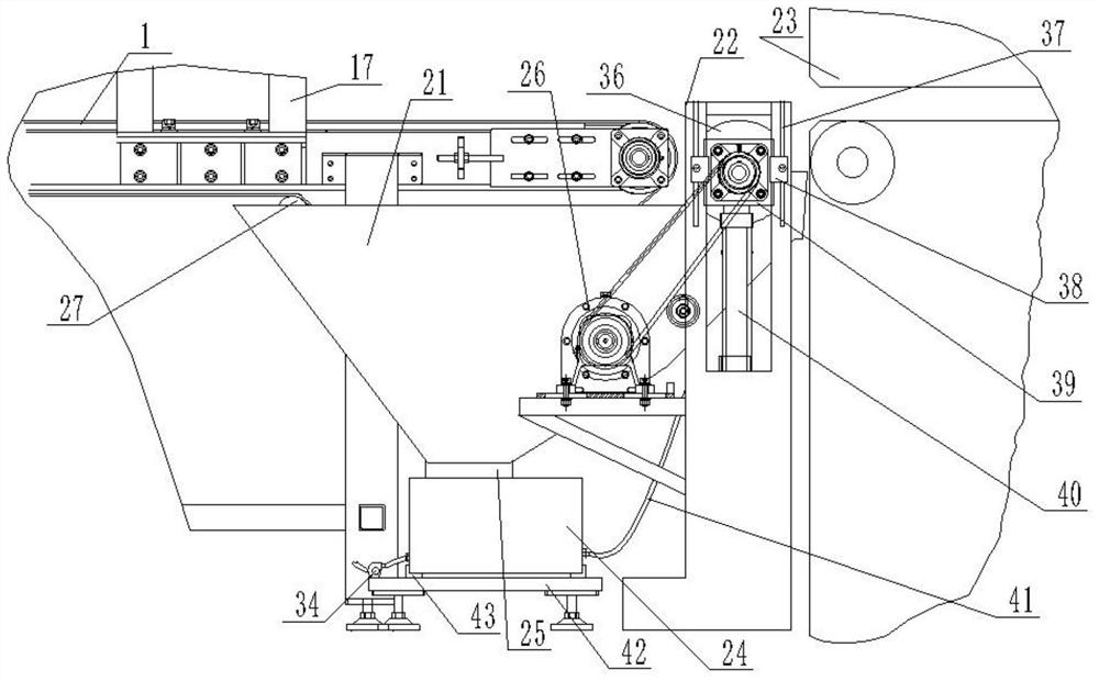
[0038] Example 2, as Figure 1-12 As mentioned above, on the basis of Embodiment 1, the front and rear sides between the conveyor 1 and the pressing device 23 are provided with support columns 22, and the support columns 22 on the front and rear sides are provided with adjustment sliders 40 that can slide up and down, The bottom of the adjustment slider 40 is fixed with an adjustment cylinder 40, and a lower cleaning roller 36 is rotatably installed between the adjustment sliders 40 on both sides through a bearing seat. The lower cleaning roller 36 is provided with lower cleaning brushes, and one end of the lower cleaning roller 36 is connected with a The cleaning drive device is provided with a dust receiving box 21 below the lower cleaning bristles.

[0039] The outer wall of the support column 22 is provided with a T-shaped chute 37 along the vertical direction, the T-shaped chute 37 is provided with a T-shaped bolt, the T-shaped bolt is connected with a locking block 39, a...


PUM


Abstract

The invention relates to an automatic conveying, flipping and capping device for clean boards, which comprises a conveyor arranged at the left end of the pressing device; The slide rails on both sides are provided with sliders, the sliders on the front and rear sides are fixedly connected through the connecting bottom plate, and the bottom plate is provided with a driving device that drives the left and right movement. There is a lifting and turning suction device, a lifting cylinder is fixed on the front and rear side frames of the conveyor on the right side of the support frame, and a limit baffle is fixed on the top of the lifting cylinder. In the present invention, support plates are arranged on both sides of the conveyor that can clamp the rear color-coated plate to rise and then turn over, and then move the color-coated plate to the front of the color-coated plate through the left and right driving devices. Coating the plate to cover and close, realize automatic cover and close, save manpower, improve efficiency and reduce labor intensity.

Description

technical field [0001] The invention belongs to the technical field of intelligent basic manufacturing equipment, and in particular relates to an automatic conveying, flipping, and capping device for clean boards. Background technique [0002] The clean board, also known as the clean board, is a composite board made of color-coated board, color steel plate and other materials as the surface material. The clean board has unique dust-proof, anti-static, anti-bacterial and other effects. It is widely used in electronics, pharmaceuticals, food, biology, aerospace, precision instrument manufacturing and scientific research and other clean engineering fields that require harsh indoor environments. Clean board is a kind of building material product with special functions such as antibacterial, anti-fouling, cleaning, etc. During the production of clean board, the color-coated board will be cut off, then the edge will be folded into a groove, and then put on the conveyor after gluin...

Claims


Application Information

Patent Timeline
Patent Type & Authority Patents(China)
IPC IPC(8): B29C65/56B29C65/64B29C65/78B08B1/00B08B1/02B65G45/12B65G45/22B29L7/00
CPCB29C65/565B29C65/64B29C65/787B29C66/0222B08B1/02B08B1/002B65G45/12B65G45/22B29L2007/002Y02W30/82
Inventor 王茂柳程乐香巩芳英王文博王文轲高瑞
Owner 山东晶承净化科技有限公司
Why Eureka
Try Eureka