Eureka AIR delivers breakthrough ideas for toughest innovation challenges, trusted by R&D personnel around the world.

Anchor rod anchoring parameter nondestructive testing device and method based on continuous beam vibration

A non-destructive testing and bolting technology, which is applied in the direction of measuring devices, processing detection response signals, and using sound waves/ultrasonic waves/infrasonic waves to analyze solids, etc. It can solve the problems of low waveform recognizability, many waveform clutter, and short exposed sections of bolts, etc. problem, to achieve the effect of simple non-destructive testing waveform recognition process, accurate detection results, and high image recognition

Pending Publication Date: 2021-08-17
HUNAN UNIV OF SCI & TECH
View PDF0 Cites 2 Cited by
  • Summary
  • Abstract
  • Description
  • Claims
  • Application Information

AI Technical Summary

Problems solved by technology

[0003] On the one hand, the exposed end surface of the anchor rod is easily damaged and uneven during transportation and anchoring, and the diameter of the commonly used anchor rod is small, so in the actual detection work, the accuracy of the detection results is restricted; on the other hand, After the anchoring is completed, the exposed section of the anchor rod may be short, and the waveform obtained by the excitation may be less recognizable
The above problems make it difficult for the inspector to operate and the obtained waveform has a lot of clutter, resulting in unnecessary errors and there is currently no physical filtering technology

Method used


Image

  • Anchor rod anchoring parameter nondestructive testing device and method based on continuous beam vibration
  • Anchor rod anchoring parameter nondestructive testing device and method based on continuous beam vibration
  • Anchor rod anchoring parameter nondestructive testing device and method based on continuous beam vibration

Examples


Embodiment Construction

[0066] In order to make the technical problems, technical solutions and beneficial effects solved by the present invention clearer, the present invention will be further described in detail below in conjunction with the accompanying drawings and embodiments. It should be understood that the specific embodiments described here are only used to explain the present invention, not to limit the present invention.

[0067] When ordinal numerals such as "first" and "second" are mentioned in the embodiments of the present invention, unless they really express the meaning of order according to the context, it should be understood that they are only used for distinction.

[0068] In the description of the present invention, it should be noted that unless otherwise specified and limited, the terms "installation", "connection" and "connection" should be understood in a broad sense, for example, it can be a fixed connection or a detachable connection. Connected, or integrally connected; it...


PUM


Abstract

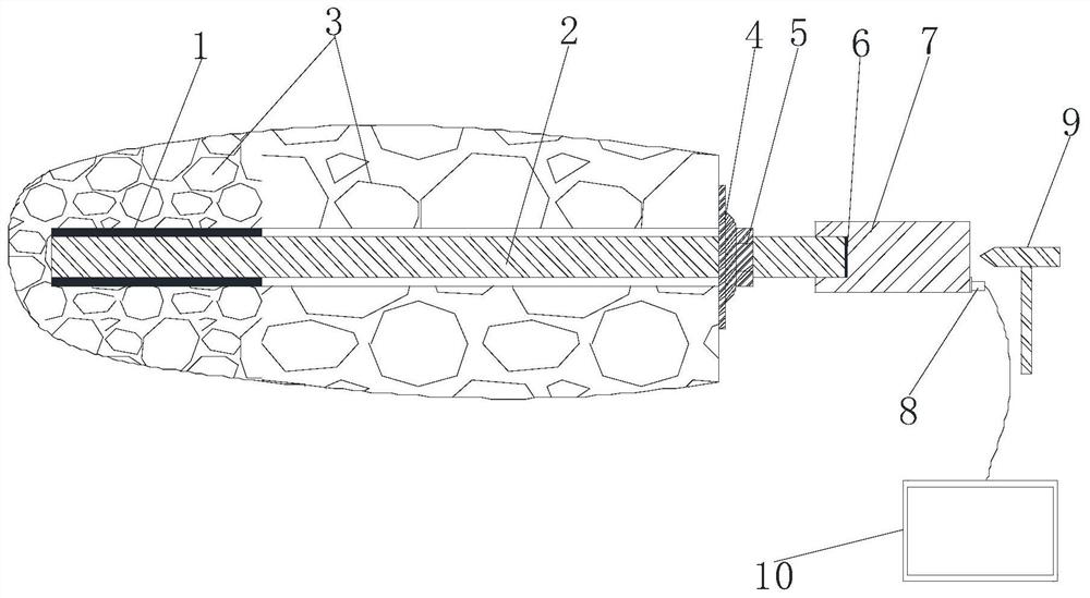
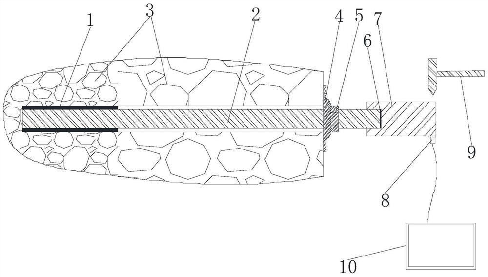
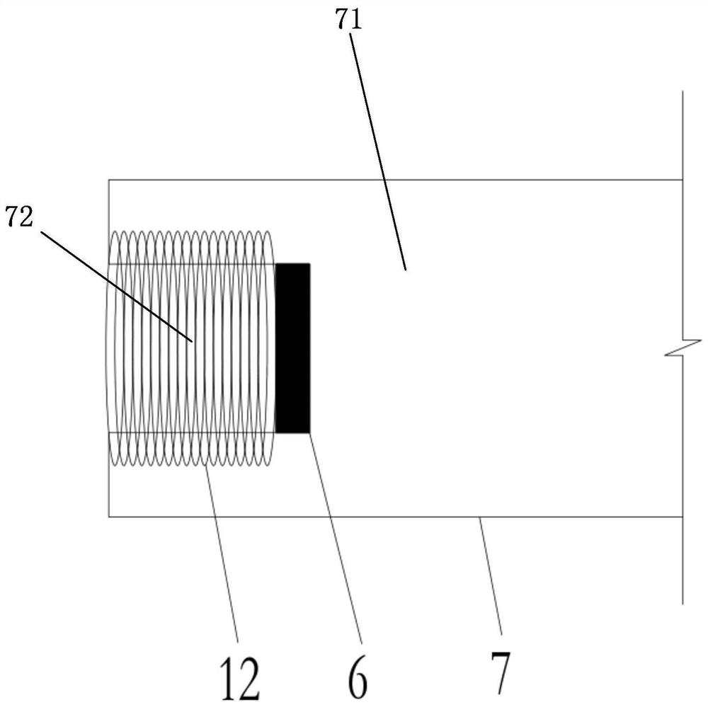
The invention relates to an anchor rod anchoring parameter nondestructive testing device and method based on continuous beam vibration. Based on a continuous beam theory, a detection auxiliary rod with a flat end face and a large diameter is additionally mounted on an exposed section of an anchor rod to be tested, and the length and the sectional area of the exposed section of the anchor rod are increased; when an excitation hammer is adopted to act on the detection auxiliary rod in the axial direction of the detection auxiliary rod, non-longitudinal clutter generated by a filtering structure of the detection auxiliary rod is detected, and due to the fact that the sectional area of the detection auxiliary rod is larger and smoother, the detection auxiliary rod can be highly coupled with an acceleration sensor, detection is more convenient, and the result is more accurate; when the excitation hammer acts on the detection auxiliary rod along the radial direction of the detection auxiliary rod, the detection auxiliary rod increases the transverse bending degree of the exposed end structure of the anchor rod and the bending moment of the supporting plate disc, so that the image recognition degree is higher, the detection result is more accurate, and meanwhile, the previous filtering means and noise reduction means can be omitted.

Description

【Technical field】 [0001] The invention relates to a device and method for non-destructive detection of bolt anchorage parameters based on continuous beam vibration. 【Background technique】 [0002] Bolt support technology is becoming more and more mature, and bolt nondestructive testing technology, as the main detection method of bolt anchorage quality in engineering, has gradually been widely used in mining and geotechnical engineering fields, but there are still many problems in bolt nondestructive testing technology urgent to overcome. [0003] On the one hand, the exposed end surface of the anchor rod is easily damaged and uneven during transportation and anchoring, and the diameter of the commonly used anchor rod is small, so in the actual detection work, the accuracy of the detection results is restricted; on the other hand, After the anchoring is completed, the exposed section of the anchor rod may be short, and the waveform obtained by the excitation may be less reco...

Claims


Application Information

Patent Timeline
Patent Type & Authority Applications(China)
IPC IPC(8): G01N29/04G01N29/22G01N29/44
CPCG01N29/045G01N29/22G01N29/44G01N2291/023G01N2291/2626
Inventor 李青锋张建业卢清芹
Owner HUNAN UNIV OF SCI & TECH
Why Eureka
Eureka Blog
Learn More