
Electrolyte injection device in a lithium-ion battery

A lithium-ion battery and injection device technology, which is applied in the manufacture of secondary batteries, battery pack components, and electrolyte storage batteries, can solve problems such as time-consuming and labor-consuming, and restrict enterprise production efficiency and production benefits, and achieve ingenious structure and design Reasonable, easy-to-use effect

Active Publication Date: 2022-04-19
WUHU ETC BATTERY LTD
View PDF0 Cites 0 Cited by
  • Summary
  • Abstract
  • Description
  • Claims
  • Application Information

AI Technical Summary

Problems solved by technology

This process is seriously time-consuming and labor-intensive, which restricts the production efficiency and production benefits of related enterprises.

Method used


Image

  • Electrolyte injection device in a lithium-ion battery
  • Electrolyte injection device in a lithium-ion battery
  • Electrolyte injection device in a lithium-ion battery

Examples


Embodiment Construction

[0036] In order to make the technical means, creative features, goals and effects achieved by the present invention easy to understand, the present invention will be further described below in conjunction with specific embodiments.

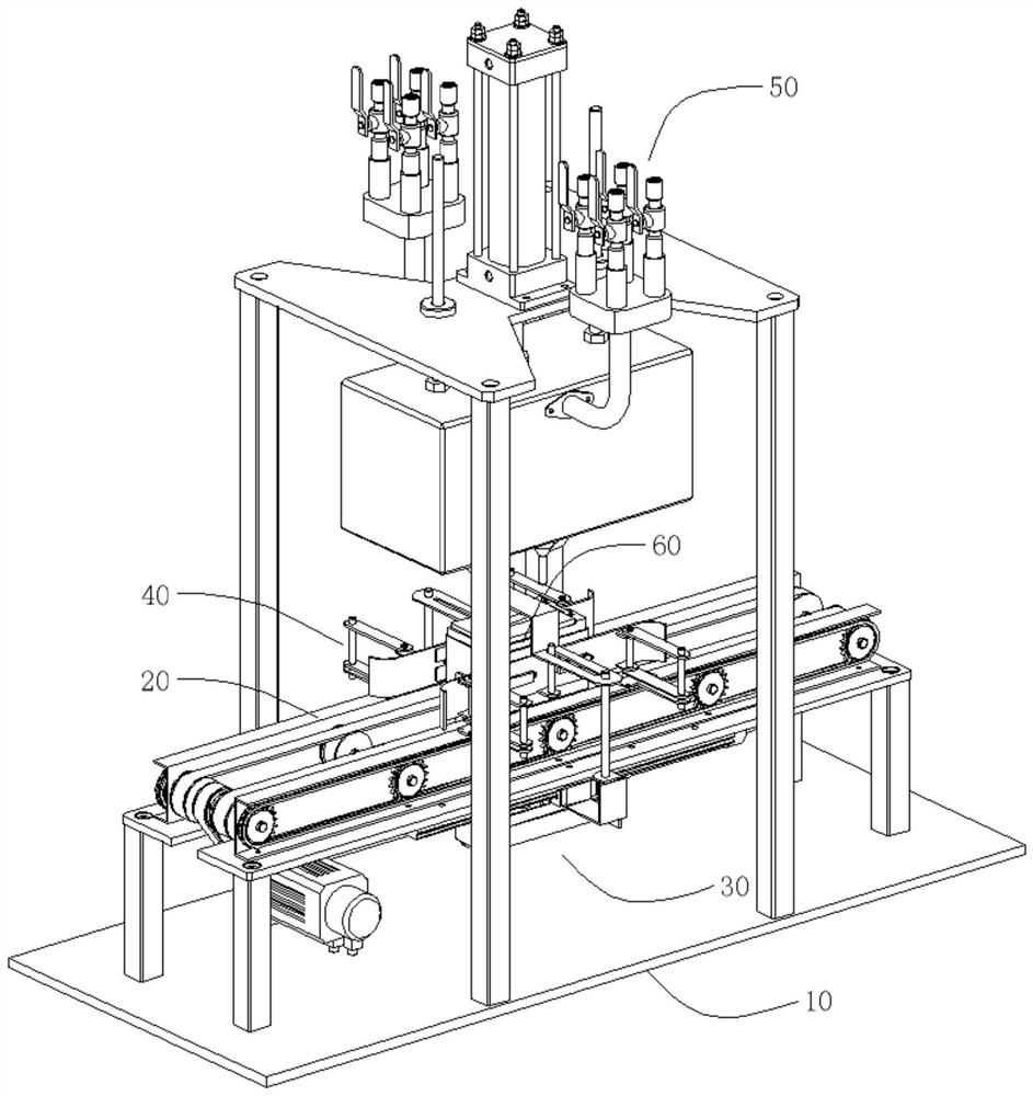
[0037] Such as Figure 1 to Figure 9 As shown, an electrolyte injection device in a lithium-ion battery includes a workbench 10, a conveying mechanism 20, a positioning mechanism 30, a clamping mechanism 40 and a liquid injection mechanism 50, wherein:

[0038] The workbench 10 is set horizontally;

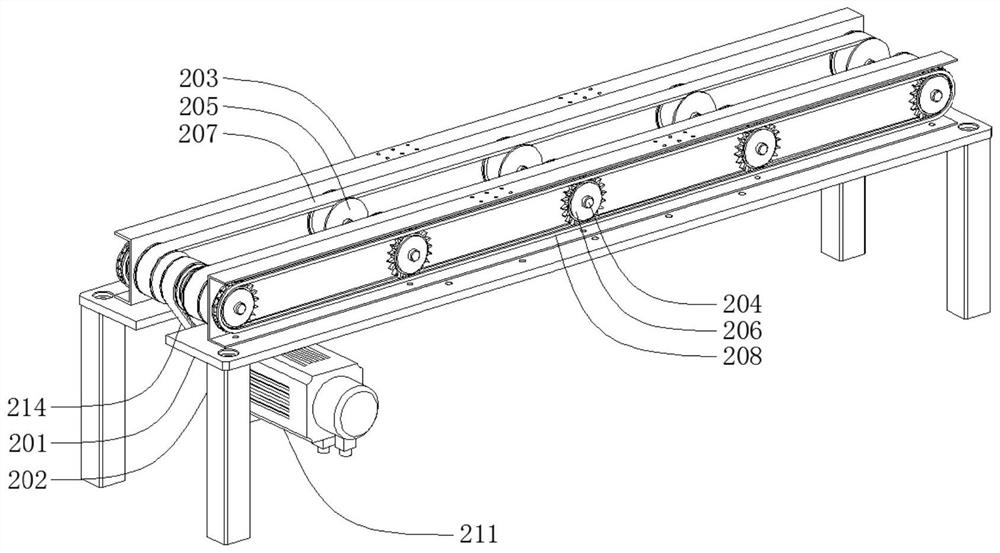
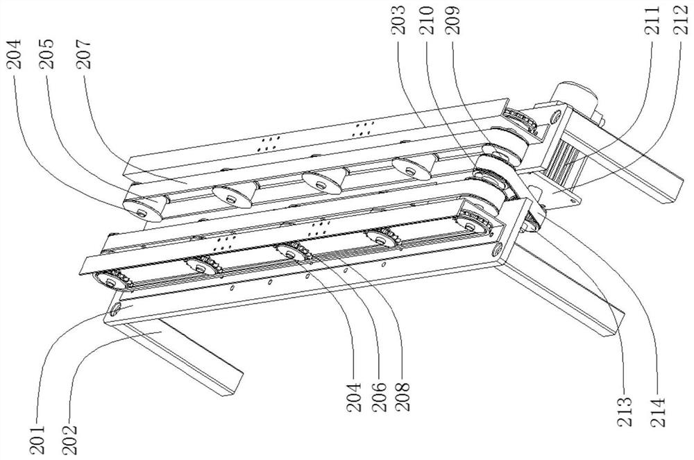
[0039]The conveying mechanism 20 is arranged on the upper side of the workbench 10 and is used to realize the conveying of the lithium battery 60 before and after the liquid injection. Motor 211 and fixed plate 1 212;

[0040] The positioning mechanism 30 is arranged on the lower side of the conveying mechanism 20 and is used to realize the positioning when the lithium battery 60 is injected. The positioning mechanism 30 specifically includes a tele...


PUM


Abstract

The invention discloses an electrolyte injection device in a lithium ion battery, relates to the technical field of lithium battery production, and includes a workbench, a conveying mechanism, a positioning mechanism, a clamping mechanism and a liquid injection mechanism, wherein the conveying mechanism is arranged on the workbench The upper side is used to realize the delivery before and after the lithium battery injection. The delivery mechanism includes a support plate and a drive motor. The positioning mechanism is located on the lower side of the delivery mechanism and is used to realize the positioning of the lithium battery injection. The positioning mechanism includes a telescopic cylinder. , Hinge strip 1, Hinge strip 2, and positioning strip. The clamping mechanism is located on the upper side of the conveying mechanism and is used to clamp the lithium battery when liquid is injected. The clamping mechanism includes an overhang strip, a clamping plate, and a hinge strip 3. , a linkage column and a linkage strip. The liquid injection mechanism is arranged on the upper side of the clamping mechanism and is used to realize the liquid injection of the lithium battery. The liquid injection mechanism includes a hydraulic cylinder and an electrolyte tank. In summary, the present invention can realize automatic delivery, automatic positioning, automatic clamping and automatic filling of lithium batteries.

Description

technical field [0001] The invention relates to the technical field of lithium battery production, in particular to an electrolyte injection device for lithium ion batteries. Background technique [0002] Electrolyte is the medium used in chemical batteries, electrolytic capacitors, etc., providing ions for their normal operation. Electrolyte is an essential part of chemical batteries, so a suitable electrolyte injection device is also essential. [0003] At present, most of the battery electrolyte injection methods on the market use the method of assembly line operation, and often need manual assistance to move the battery from the conveying line to the liquid injection station, and the liquid injection can only be performed after the corresponding positioning tool is placed. After the liquid is filled, the battery is moved back from the filling station to the conveying line. This process is seriously time-consuming and labor-intensive, which restricts the production effi...

Claims


Application Information

Patent Timeline
Patent Type & Authority Patents(China)
IPC IPC(8): H01M50/609H01M50/618H01M10/058H01M10/0525
CPCH01M10/058H01M10/0525Y02P70/50Y02E60/10
Inventor 路宝詹新举窦元运
Owner WUHU ETC BATTERY LTD
Learn More