
Retaining ring for chemical mechanical polishing

A technology of chemical machinery and retaining rings, which is applied in the direction of grinding/polishing equipment, grinding machine tools, working carriers, etc., and can solve the problem of mixing polishing fluid and grinding debris

Active Publication Date: 2021-08-20
BEIJING SEMICORE PRECISION MICROELECTRONICS EQUIP CO LTD
View PDF6 Cites 2 Cited by
  • Summary
  • Abstract
  • Description
  • Claims
  • Application Information

AI Technical Summary

Problems solved by technology

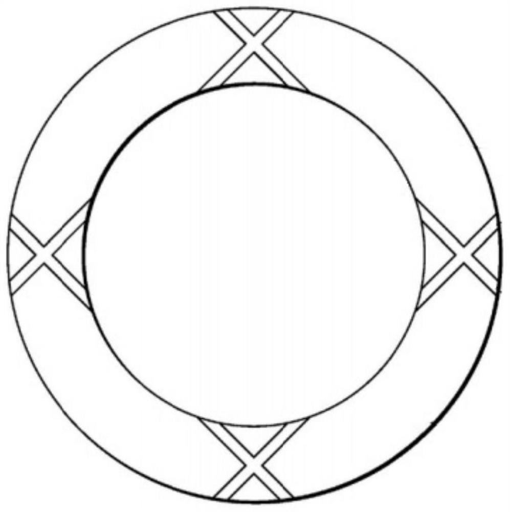
[0004] Therefore, the technical problem to be solved by the present invention is to overcome the defect that the intersecting grooves on the retaining ring in the prior art have intersection points that are easy to mix the polishing liquid and the grinding debris, thereby providing a retaining ring for chemical mechanical polishing.

Method used


Image

  • Retaining ring for chemical mechanical polishing
  • Retaining ring for chemical mechanical polishing
  • Retaining ring for chemical mechanical polishing

Examples


Embodiment Construction

[0038] The technical solutions of the present invention will be clearly and completely described below in conjunction with the accompanying drawings. Apparently, the described embodiments are some of the embodiments of the present invention, but not all of them. Based on the embodiments of the present invention, all other embodiments obtained by persons of ordinary skill in the art without making creative efforts belong to the protection scope of the present invention.

[0039] In the description of the present invention, it should be noted that the terms "center", "upper", "lower", "left", "right", "vertical", "horizontal", "inner", "outer" etc. The indicated orientation or positional relationship is based on the orientation or positional relationship shown in the drawings, and is only for the convenience of describing the present invention and simplifying the description, rather than indicating or implying that the referred device or element must have a specific orientation, ...


PUM


Abstract

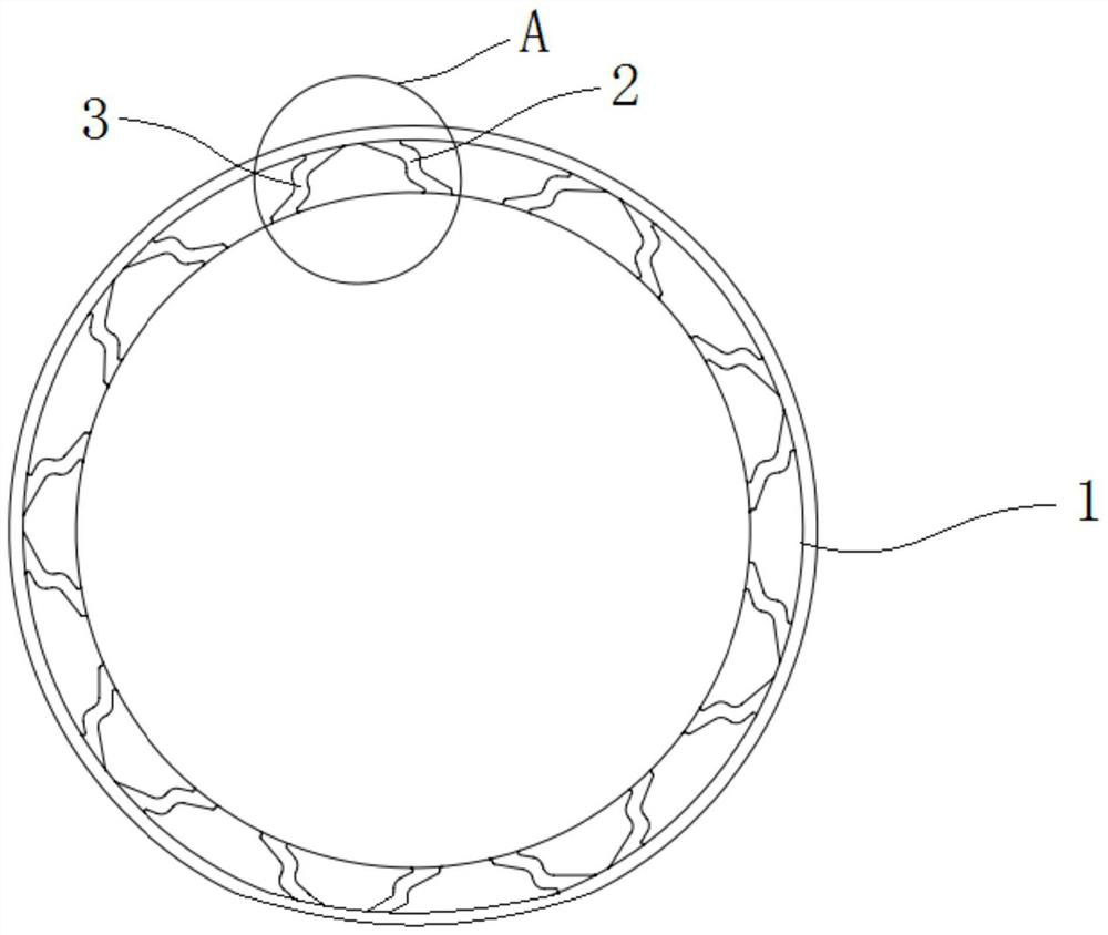
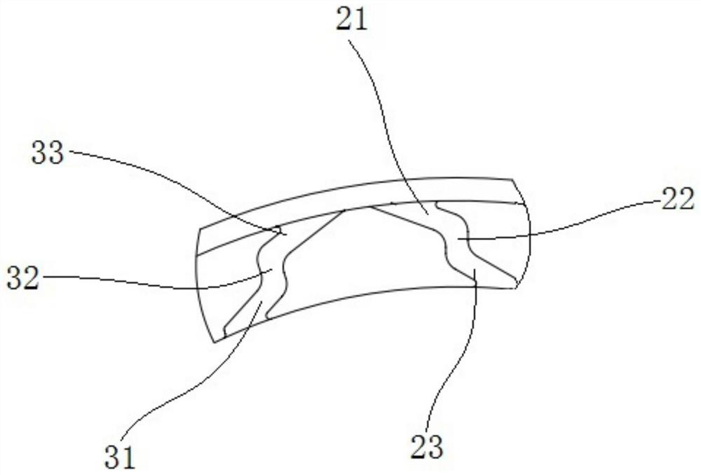
The invention provides a retaining ring for chemical mechanical polishing, and belongs to the technical field of chemical mechanical polishing equipment. The retaining ring comprises a retaining ring body in a circular ring shape, multiple sets of grooves penetrating through the outer circumference and the inner circumference of the retaining ring body are formed in the bottom surface of the retaining ring body, and the sets of grooves are arranged at intervals; each set of grooves are provided with a liquid guiding groove and a chip discharging groove which are opposite in inclination direction, and the liquid guiding grooves and the chip discharging grooves are independently arranged; and in the rotating direction of the retaining ring body, the outlets of the liquid guide grooves are inclined towards the rear part of the rotating direction. According to the retaining ring for chemical mechanical polishing, the multiple sets of grooves are formed in the annular retaining ring body, each set of grooves comprise the liquid guiding groove and the chip discharging groove which are opposite in inclination direction, and the liquid guiding grooves and the chip discharging grooves are independently formed, so that suction of polishing liquid and discharging of grinding chips are achieved; and meanwhile, the polishing solution and the grinding scraps are prevented from being mixed in the grooves, and the grinding effect of a wafer is guaranteed.

Description

technical field [0001] The invention relates to the technical field of chemical mechanical polishing equipment, in particular to a retaining ring for chemical mechanical polishing. Background technique [0002] The integrated circuit manufacturing process generally refers to depositing conductors, semiconductors, and insulating layers on a specific substrate (such as a silicon wafer) in a certain process sequence. During the manufacturing process, chemical mechanical planarization (CMP) equipment is mainly used to globally planarize the microscopically rough surface of the wafer after the film deposition process. This planarization method usually requires mounting the wafer on the polishing head of the CMP equipment, and placing the wafer on the side to be polished against a rotating polishing pad. The retaining ring clamps the wafer on the polishing head to prevent the wafer from being thrown out during polishing, and there is a groove on the surface of the retaining ring ...

Claims


Application Information

Patent Timeline
Patent Type & Authority Applications(China)
IPC IPC(8): B24B37/32B24B37/34B24B57/02
CPCB24B37/32B24B37/34B24B57/02
Inventor 尹影刘晓亮庞浩
Owner BEIJING SEMICORE PRECISION MICROELECTRONICS EQUIP CO LTD
Learn More