
Continuous beam bridge with separation support with self-resetting function

A function separation and self-resetting technology, which is applied to bridges, bridge construction, bridge parts, etc., can solve problems such as difficult self-resetting, easy repair, unfavorable post-disaster rescue access, and difficult repair.

Pending Publication Date: 2021-08-20
BEIJING UNIV OF TECH
View PDF0 Cites 0 Cited by
  • Summary
  • Abstract
  • Description
  • Claims
  • Application Information

AI Technical Summary

Problems solved by technology

[0002] In order to improve the seismic performance of continuous girder bridges, the ductile anti-seismic design concept and seismic isolation technology are widely used, but the residual deformation of the traditional ductile anti-seismic design is too large after the earthquake, which is not easy to repair, which is not conducive to post-disaster rescue. Under the action of strong earthquakes, the bearings are often damaged due to excessive horizontal relative displacement, not only losing the horizontal energy consumption and shock absorption function, but also the vertical bearing capacity cannot meet the requirements, and due to the large vertical bearing tonnage and complex structure, replacement is very difficult difficulty
At the same time, in the above-mentioned seismic design method, the components that undertake normal service functions and the components that undertake earthquake action are mostly the same component, and are combined in a "series" manner, which lacks graded response characteristics and dynamic protection capabilities, and it is difficult to achieve strong earthquake protection. Rear self-resetting, easy-to-repair seismic fortification target

Method used


Image

  • Continuous beam bridge with separation support with self-resetting function
  • Continuous beam bridge with separation support with self-resetting function
  • Continuous beam bridge with separation support with self-resetting function

Examples


Embodiment Construction

[0044] The following will clearly and completely describe the technical solutions in the embodiments of the present invention with reference to the accompanying drawings in the embodiments of the present invention. Obviously, the described embodiments are only some, not all, embodiments of the present invention. Based on the embodiments of the present invention, all other embodiments obtained by persons of ordinary skill in the art without making creative efforts belong to the protection scope of the present invention.

[0045] In order to make the above objects, features and advantages of the present invention more comprehensible, the present invention will be further described in detail below in conjunction with the accompanying drawings and specific embodiments.

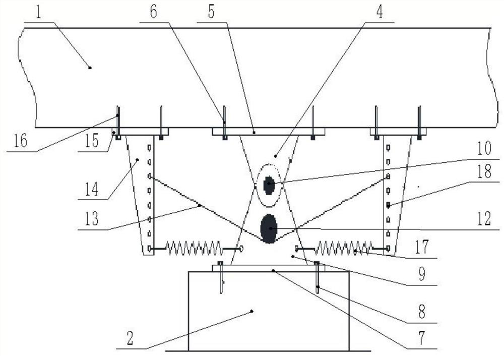
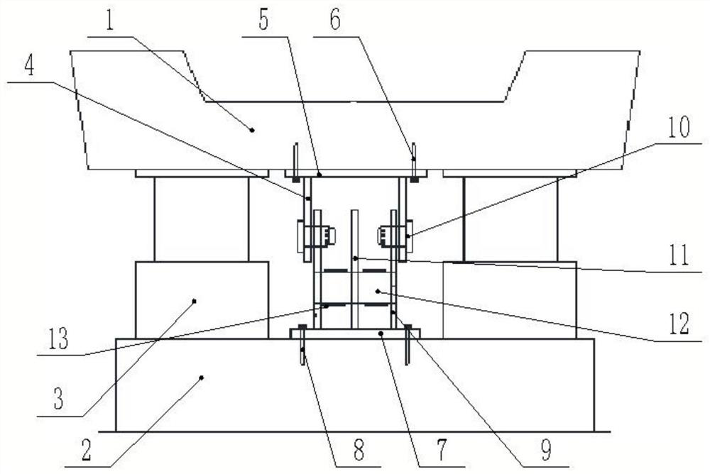
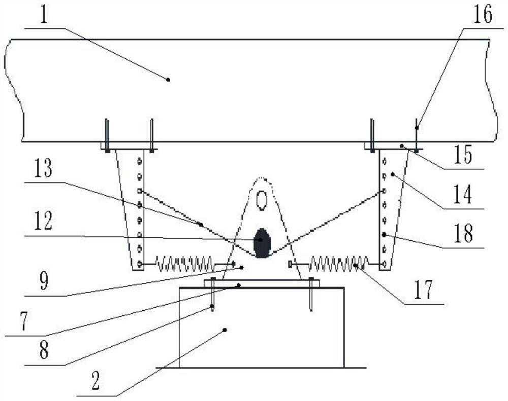
[0046] The present invention provides a continuous girder bridge with self-resetting functional separation support, which includes a main girder 1, bridge pier 2 and self-resetting function separation support, and ...


PUM


Abstract

The invention discloses a self-resetting function separation support continuous beam bridge, and the beam bridge comprises a main beam, a pier and a self-resetting function separation support; the self-resetting function separation support comprises a sliding support and a self-resetting energy consumption connecting device, and the self-resetting energy consumption connecting device is divided into a sliding type self-resetting energy consumption connecting device and a locking type self-resetting energy consumption connecting device; after the state locking mechanism is removed, the locking type self-resetting energy consumption connecting device forms the sliding type self-resetting energy consumption connecting device. The beam bridge has a grading response mechanism for frequent earthquakes, accidental earthquakes and rare or extremely rare earthquakes; and when the earthquake force is large enough, the locking type self-resetting energy dissipation connecting device is changed into a sliding type self-resetting energy dissipation connecting device. The self-resetting function separation support continuous beam bridge can utilize the anti-seismic potential of the movable piers, all the piers share seismic energy together, and finally the structure returns to the initial position under the combined action of the seismic complementary energy and the restoring force springs.

Description

technical field [0001] The invention relates to the technical field of bridge construction, in particular to a continuous girder bridge with self-resetting functional separation supports. Background technique [0002] In order to improve the seismic performance of continuous girder bridges, the ductile anti-seismic design concept and seismic isolation technology are widely used, but the residual deformation of the traditional ductile anti-seismic design is too large after the earthquake, which is not easy to repair, which is not conducive to post-disaster rescue. Under the action of strong earthquakes, the bearings are often damaged due to excessive horizontal relative displacement, not only losing the horizontal energy consumption and shock absorption function, but also the vertical bearing capacity cannot meet the requirements, and due to the large vertical bearing tonnage and complex structure, replacement is very difficult difficulty. At the same time, in the above-ment...

Claims


Application Information

Patent Timeline
Patent Type & Authority Applications(China)
IPC IPC(8): E01D19/00E01D19/04
CPCE01D19/00E01D19/04E01D19/042
Inventor 梁昆谭豫卿张孟琦张成张文学郑永瑞汪志斌
Owner BEIJING UNIV OF TECH
Learn More