A Method of Using Laser Altimeter Points as Image Elevation Control Points in Undulating Surface Areas

A technology of elevation control point and height measurement point, which is applied in measurement devices, surveying and navigation, height/level measurement, etc., can solve the waste of resources, idle waste of laser height measurement points, and inability to obtain high-precision elevation values ​​of ground footprints, etc. problems, to achieve great economic and social benefits, improve usability and effectiveness, and achieve the effect of accurate pixel positions

Active Publication Date: 2021-11-09
自然资源部国土卫星遥感应用中心
View PDF2 Cites 0 Cited by
  • Summary
  • Abstract
  • Description
  • Claims
  • Application Information

AI Technical Summary

Problems solved by technology

In all previous studies, the center point of the ground footprint of the laser altimetry point is generally used as the elevation control point of the stereo image. The high-precision elevation value of the center point of the ground footprint can be obtained. Therefore, in the past, only the smooth laser altimetry points within the range of the ground footprint can be selected as the stereoscopic image control, and the surface relief within the footprint range (that is, terrain fluctuations or The use of laser altimetry points with different elevations) has great limitations in the use of laser altimetry points, and a large number of laser altimetry points within the range of ground footprints are forced to abandon, resulting in huge waste of resources
However, areas with undulating terrain are often areas where other types of high-precision ground control points are relatively scarce, which also reduces the applicability and practicability of laser altimetry points as elevation control points for stereo images
To sum up, the problem existing in the current technology is: the conventional method of using laser altimetry points as elevation control is to use the center point of the ground footprint of the laser altimetry point as the elevation control point of the stereoscopic image, which leads to the distribution on the surface undulations (that is, terrain The laser altimetry points in the undulating, complex terrain) area cannot be applied to the stereoscopic image elevation control because of the inability to obtain the high-precision elevation value of the center point of the ground footprint, resulting in a large number of idle waste of the laser altimetry points, resulting in the loss of the laser altimetry points The utilization efficiency in complex areas on the surface is extremely low
[0004] Therefore, designing an effective method that can make full use of the laser altimetry points in the undulating area as the elevation control points of the stereo image is to solve the problem that the laser altimetry points in the undulating area cannot be effectively applied to the elevation control of the stereo image, and improve the whole area. The urgent need for the utilization of laser altimetry points will also create greater social and economic benefits

Method used


Image

  • A Method of Using Laser Altimeter Points as Image Elevation Control Points in Undulating Surface Areas
  • A Method of Using Laser Altimeter Points as Image Elevation Control Points in Undulating Surface Areas
  • A Method of Using Laser Altimeter Points as Image Elevation Control Points in Undulating Surface Areas

Examples


Embodiment Construction

[0018] In order to make the object, technical solution and advantages of the present invention clearer, the present invention will be further described in detail below in conjunction with the embodiments and accompanying drawings.

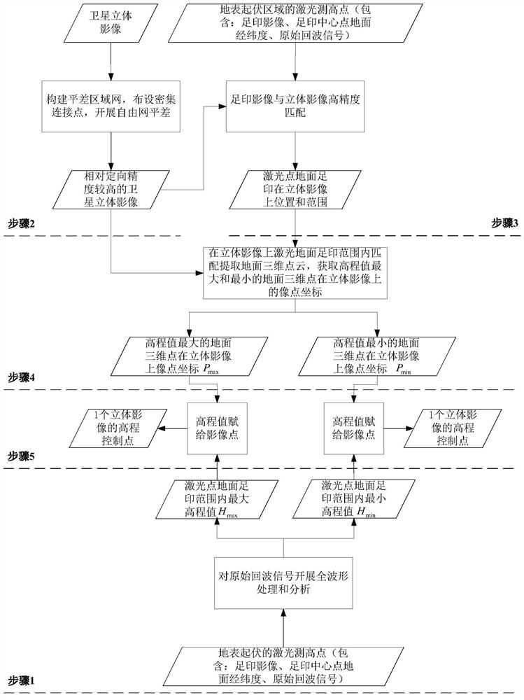
[0019] Such as figure 1 As shown, the laser altimetry point in the surface undulation area provided by the present invention is used as the image elevation control point method, comprising the following steps:

[0020] Step 1. Carry out full waveform processing and analysis on the original echo signal of the laser altimetry point located in the undulating surface area, obtain the elevation values ​​of multiple different heights of the surface within the ground footprint range of the laser altimetry point, and count the maximum elevation value of the surface h max and minimum elevation value H min ;

[0021] In areas with undulating surfaces, the Gaussian waveform laser pulses emitted by the laser altimeter will be reflected multiple times by obj...


PUM


Abstract

The invention discloses a method for using a laser altimetry point in an undulating surface area as an image elevation control point. Firstly, full waveform processing is performed on the echo signal of a laser point in the undulating surface area to obtain the maximum and minimum elevation values ​​of the ground surface in the ground footprint of the laser point. Then use the high-precision registration of the laser footprint image and the stereo image to obtain the range of the ground footprint of the laser point on the stereo image. Then, image dense matching is carried out within the range of the ground footprint of the laser point on the stereoscopic image to generate a 3D point cloud on the ground, and the corresponding image point coordinates of the 3D ground points with the largest and smallest elevation values ​​on the stereoscopic image are obtained. Finally, the maximum and minimum elevation values ​​of the ground surface in the ground footprint of the laser point are assigned to them respectively, that is, two elevation control points on the stereoscopic image are obtained through one laser point. The invention breaks through the previous limitation that the laser point in the surface undulation area cannot be used for elevation control because the accurate elevation of the center point of the footprint cannot be obtained, and greatly improves the utilization rate of the laser point in the surface undulation area.

Description

technical field [0001] The invention belongs to the technical field of remote sensing and photogrammetry, and in particular relates to a method for using laser altimetry points in a surface undulating area as elevation control points for stereo images. Background technique [0002] As a high-precision ranging instrument, the existing laser altimeter can obtain high-precision surface elevation information because of its good directionality and high ranging accuracy. Currently available spaceborne laser altimetry data mainly include two types, one is the laser altimetry point data obtained by special laser altimetry satellites, such as the Geoscience Laser Altimeter System carried on the ICESat satellite launched by the country in 2003 Laser point altimeter data; Laser altimeter data obtained by the Advanced Topographic Laser Altimeter System on the ICESat-02 satellite launched by xx in 2018. The other is the stereo mapping satellite equipped with an optical stereo camera and...

Claims


Application Information

Patent Timeline
Patent Type & Authority Patents(China)
IPC IPC(8): G01C5/00G01C11/00
CPCG01C5/00G01C11/00
Inventor 周平唐新明刘昌儒陈颖郭莉王霞张恒李国元
Owner 自然资源部国土卫星遥感应用中心
Why Eureka
Try Eureka