
Over-the-horizon target direct positioning method based on short-wave multi-station angles and satellite time frequency

An over-the-horizon, short-wave technology, applied in positioning, radio wave measurement systems, measurement devices, etc., can solve the problems of multiple intermediate parameters and limited positioning accuracy, and achieve reliable performance, improved positioning accuracy, and efficient calculations.

Pending Publication Date: 2021-08-20
PLA STRATEGIC SUPPORT FORCE INFORMATION ENG UNIV PLA SSF IEU
View PDF0 Cites 0 Cited by
  • Summary
  • Abstract
  • Description
  • Claims
  • Application Information

AI Technical Summary

Problems solved by technology

[0005] Aiming at the problems of limited positioning accuracy and many intermediate parameters that need to be calculated in the existing radio signal positioning methods, the present invention provides a direct positioning method for over-the-horizon targets that coordinates short-wave multi-station angles and satellite time-frequency, which can Significantly improve the positioning accuracy of the over-the-horizon (long-distance) radiation source on the earth's surface, and realize it through the Newton-type iterative formula, which has a faster convergence speed, no need for grid search, and efficient operation

Method used


Image

  • Over-the-horizon target direct positioning method based on short-wave multi-station angles and satellite time frequency
  • Over-the-horizon target direct positioning method based on short-wave multi-station angles and satellite time frequency
  • Over-the-horizon target direct positioning method based on short-wave multi-station angles and satellite time frequency

Examples


Embodiment Construction

[0075] In order to make the purpose, technical solutions and advantages of the present invention clearer, the technical solutions in the embodiments of the present invention will be clearly described below in conjunction with the accompanying drawings in the embodiments of the present invention. Obviously, the described embodiments are part of the present invention Examples, not all examples. Based on the embodiments of the present invention, all other embodiments obtained by persons of ordinary skill in the art without making creative efforts belong to the protection scope of the present invention.

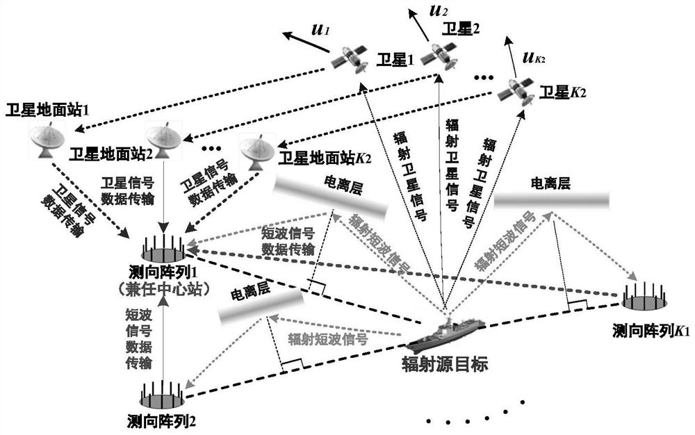
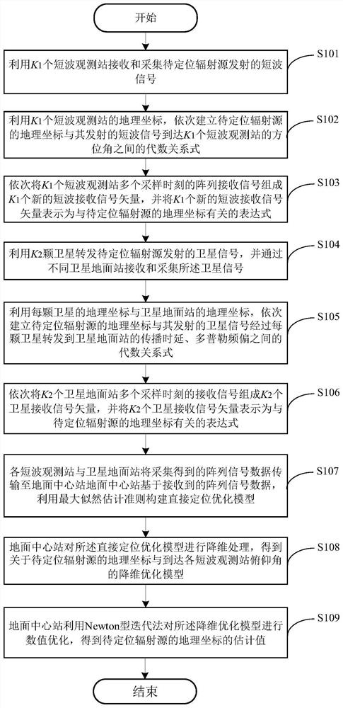
[0076] combine figure 1 with figure 2 , the embodiment of the present invention provides a method for direct positioning of an over-the-horizon target in coordination with short-wave multi-station angles and satellite time-frequency, comprising the following steps:

[0077] S101: Use K 1 A shortwave observation station (an array installed at the observation station capable of...


PUM


Abstract

The invention provides an over-the-horizon target direct positioning method based on short-wave multi-station angles and satellite time frequency. The method comprises the following steps of: receiving and collecting short-wave signals emitted by a to-be-positioned radiation source by using a plurality of short-wave observation stations, and sequentially establishing algebraic relational expressions between the geographic coordinates of the radiation source and azimuth angles of the short-wave signals emitted by the radiation source to the different short-wave observation stations; using a plurality of satellites to forward the satellite signals emitted by the to-be-positioned radiation source, receiving and collecting the satellite signals, and are sequentially establishing algebraic relational expressions between the geographic coordinates of the radiation source and the propagation time delay and Doppler frequency offset of the satellite signals emitted by the radiation source which are forwarded to a satellite ground station through each satellite, then representing the algebraic relational expressions as an expression related to the geographic coordinates of the to-be-positioned radiation source; and making a ground center station obtain an optimization model for estimating the longitude and latitude of the radiation source based on short wave and satellite signal data, and perform numerical optimization on the optimization model to obtain a longitude and latitude estimated value of the radiation source. The method has high convergence speed and does not need grid search.

Description

technical field [0001] The invention relates to the technical field of wireless signal positioning, in particular to a direct positioning method for an over-the-horizon target by coordinating short-wave multi-station angles and satellite time-frequency. Background technique [0002] As we all know, radio signal positioning technology is very important for target discovery and situation awareness. After decades of development, this technology has made great progress in theory and engineering applications. According to the positioning means, radiolocation can be divided into satellite-based radiolocation and land-based radiolocation. Satellite-based radio positioning system, that is, satellite navigation and positioning system has a wide range of high-precision positioning, speed measurement and the ability to provide timing services, and has been widely used in various fields of national defense and national economy. In the ground-based radiolocation system, people refer to ...

Claims


Application Information

Patent Timeline
IPC IPC(8): G01S5/04
CPCG01S5/04
Inventor 尹洁昕王鼎杨宾张莉唐涛吴志东任修坤郑娜娥王成张伦东
Owner PLA STRATEGIC SUPPORT FORCE INFORMATION ENG UNIV PLA SSF IEU
Features
  • Generate Ideas
  • Intellectual Property
  • Life Sciences
  • Materials
  • Tech Scout
  • Unparalleled Data Quality
  • Higher Quality Content
  • 60% Fewer Hallucinations
Learn More