Medical portable ultrasonic scalpel, control system and use method

A control system, ultrasonic technology, applied in the direction of surgery, medical science, etc., can solve the problems of unable to feedback frequency in time, unable to guarantee resonance state, and low integration of ultrasonic scalpel, so as to achieve the effect of easy storage and carrying, and high integration

Pending Publication Date: 2021-08-24
中国人民解放军联勤保障部队第九六二医院 +2
View PDF0 Cites 0 Cited by
  • Summary
  • Abstract
  • Description
  • Claims
  • Application Information

AI Technical Summary

Problems solved by technology

[0007] In order to solve the problems that the existing ultrasonic scalpel is not highly integrated, cannot be guaranteed to be in a resonance state, and cannot feedback frequency in time, the present invention proposes a medical portable ultrasonic scalpel, a control system and a method of use; the technical scheme of the present invention is as follows:

Method used


Image

  • Medical portable ultrasonic scalpel, control system and use method
  • Medical portable ultrasonic scalpel, control system and use method
  • Medical portable ultrasonic scalpel, control system and use method

Examples


specific Embodiment approach 1

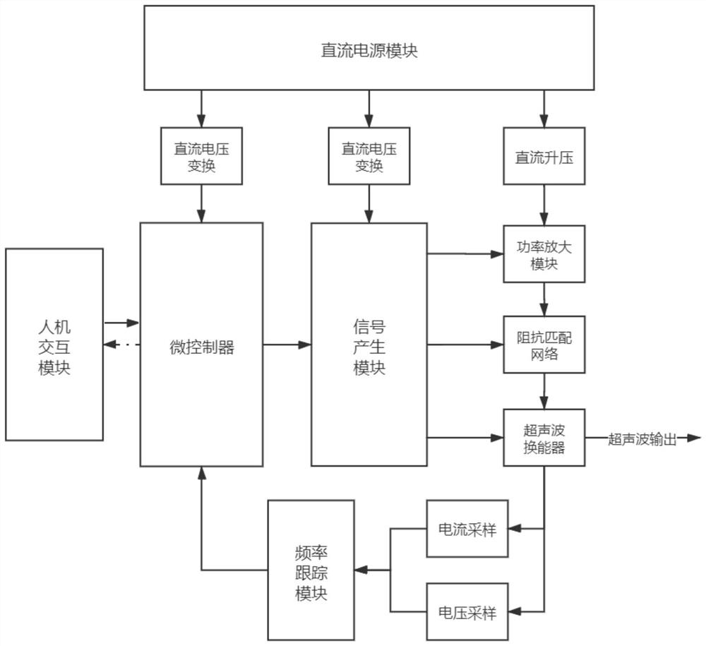
[0044] Embodiment 1: A medical portable ultrasonic scalpel and its control system, consisting of an ultrasonic transducer, an impedance matching module, a microcontroller, a signal generating module, a photoelectric isolation module, a power amplification module, a phase-locked loop circuit, a voltage and current It is composed of sampling feedback circuit, DC voltage conversion module, DC boost circuit, human-computer interaction module and charging module; the detailed implementation process is as follows:

[0045] (1) The ultrasonic transducer converts electrical energy into mechanical vibration, causing the longitudinal vibration of the ultrasonic knife rod and transmitting the energy. In the process of energy conversion, the ultrasonic knife will produce mechanical impact, cavitation effect and thermal effect. Mechanical shock will cause protein hydrogen bonds to break, and at the same time, the temperature will rise, causing local liquefaction and homogenization of biolo...

specific Embodiment approach 2

[0060] Embodiment 2: In addition to describing the modules included in a portable medical ultrasonic scalpel, this embodiment also provides a method for using a portable medical ultrasonic scalpel. The specific operation steps are as follows:

[0061] Step 1, the user starts the scalpel through the start button;

[0062] Step 2, the microprocessor issues a command, and the signal generation module sends out a signal to control power, adjust impedance matching, and activate the ultrasonic transducer to complete the ultrasonic output;

[0063] Step 3, the ultrasonic transducer feeds back current and voltage sampling information to the frequency tracking module for frequency information recording;

[0064] Step 4, feedback the frequency information to the microcontroller to form a stable ultrasonic output.

[0065] Combined with the module composition of the medical portable ultrasonic scalpel, the method steps can be refined as follows:

[0066] a. Microcontroller control proc...


PUM


Abstract

The invention discloses a medical portable ultrasonic scalpel and a use method, belongs to the technical field of ultrasonic scalpels, and aims to solve the problems that an existing ultrasonic scalpel is low in integration level, cannot be in a resonance state and cannot feed back frequency in time. The medical portable ultrasonic scalpel is composed of an ultrasonic transducer, an impedance matching module, a microcontroller, a signal generation module, a photoelectric isolation module, a power amplification module, a phase-locked loop circuit, a voltage and current sampling feedback circuit, a direct-current voltage conversion module, a direct-current booster circuit, a man-machine interaction module and a charging module. The whole impedance matching network circuit is in a pure impedance state, current and voltage sampling information is fed back to the processor in combination with the ultrasonic transducer, the scalpel is kept in a resonance state, the ultrasonic scalpel adopts modular design, and therefore the scalpel body, the scalpel head, the transducer and the battery are of a separable structure and can be rapidly assembled and disassembled when needed, and medical staff can conveniently store and carry the device.

Description

technical field [0001] The invention relates to a medical portable ultrasonic scalpel, a control system and a use method, and belongs to the technical field of ultrasonic scalpels. Background technique [0002] Ultrasonic scalpel is a high-frequency electrosurgical device, which is mainly used for cutting biological tissues and closing blood vessels. Ultrasonic scalpel has the characteristics of less bleeding, less damage to surrounding tissues, and quick postoperative recovery. It acts on human tissue with protein coagulation as the end point of the effect, and will not cause side effects such as tissue drying and burns. There is no current passing through the knife head when it is working. The human body has a wide range of applications in the operating room. [0003] The outdoor surgical environment is complex, and the traditional ultrasonic scalpel is bulky and inconvenient to carry, and requires a stable 220V AC power supply, making it difficult to deploy and use quick...

Claims


Application Information

Patent Timeline
Patent Type & Authority Applications(China)
IPC IPC(8): A61B17/32
CPCA61B17/320068A61B2017/320069A61B2017/320082
Inventor 伞锕镅朱四强刘莉陈志峰常光宇刘鑫涛关保章庞明
Owner 中国人民解放军联勤保障部队第九六二医院
Why Eureka
Try Eureka