
Multifunctional rehabilitation station

A multifunctional, panel-based technology, applied in the field of rehabilitation stations, can solve problems such as difficulty for external personnel to observe the patient's physical therapy status, inconvenient upper and lower equipment, separate rehabilitation exercises, etc., to relieve arterial vasospasm, ensure stability and safety, and improve effect on heart function

Pending Publication Date: 2021-08-24
HANGZHOU ROBOCT TECH DEV CO LTD
View PDF9 Cites 0 Cited by
  • Summary
  • Abstract
  • Description
  • Claims
  • Application Information

AI Technical Summary

Problems solved by technology

[0003] However, since the patients currently using horizontal rehabilitation trainers are generally paraplegia patients and patients in the early stage of postoperative rehabilitation, it is difficult for these patients to perform rehabilitation equipment by themselves. When the current rehabilitation equipment is aimed at such patients, the equipment is highly fixed. , leading to inconvenience when getting on and off the equipment. At the same time, according to different patients, the parts that patients need to exercise are also different. Since most of the rehabilitation equipment currently used has a single function, it is difficult to separate the legs and arms of the patient. Rehabilitation exercise, and during the exercise, since most of the rehabilitation equipment currently used is not equipped with audio equipment, it is difficult for the patient to communicate with the outside in a relatively sealed rehabilitation cabin, and it is also difficult for external personnel to observe the patient's physical therapy status

Method used


Image

  • Multifunctional rehabilitation station
  • Multifunctional rehabilitation station
  • Multifunctional rehabilitation station

Examples


Embodiment Construction

[0032] The present invention will be further described below in conjunction with the accompanying drawings and embodiments.

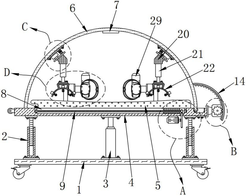
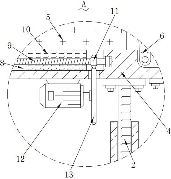
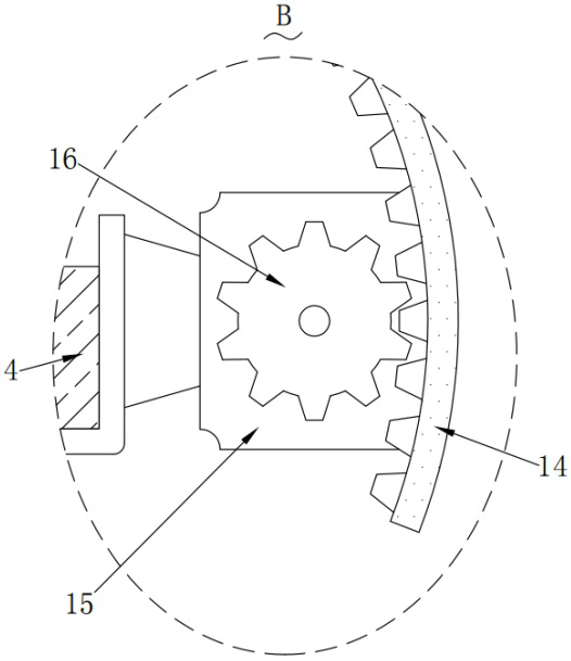
[0033] Please refer to Figure 1-Figure 10 ,in, figure 1 A schematic diagram of a closed state structure in front view and section view of a preferred embodiment of the multifunctional rehabilitation station provided by the present invention; figure 2 for figure 1 Schematic enlarged structure of part A shown in ; image 3 for figure 1 Schematic enlarged structure of part B shown in ; Figure 4 for figure 1 Schematic enlarged structure of part C shown in ; Figure 5 for figure 1 Schematic enlarged structure of part D shown in ; Image 6 A schematic diagram of a closed state structure in side view of a preferred embodiment of the multifunctional rehabilitation station provided by the present invention; Figure 7 for Image 6 Schematic enlarged structure of part E shown in ; Figure 8 for Image 6 Schematic diagram of the enlarged structure of p...


PUM


Abstract

The invention provides a multifunctional rehabilitation station. The multifunctional rehabilitation station comprises: a base; multiple correction telescopic rods, wherein the multiple correction telescopic rods of the multiple correction supports are all fixedly installed on the top of the base, and the multiple correction telescopic rods are distributed in a rectangular array mode; multiple first electric telescopic rods, wherein the multiple first electric telescopic rods as power sources and used for adjusting the height are all fixedly installed on the top of the base, and the multiple first electric telescopic rods are located among the multiple correction telescopic rods and are arranged in a staggered mode; and a panel, wherein the panel is fixedly mounted on output rods of the plurality of first electric telescopic rods. The multifunctional rehabilitation station has the advantages that the height and the position can be adjusted, the multifunctional rehabilitation station can be in butt joint with a bed of a patient, the patient can enter the rehabilitation station without obstacles, meanwhile, the legs and the arms of the patient can be exercised in a targeted mode, synchronous communication can be conducted during exercise, and people can conveniently know the physical therapy state of the patient.

Description

technical field [0001] The invention relates to the technical field of rehabilitation stations, in particular to a multifunctional rehabilitation station. Background technique [0002] Rehabilitation physiotherapy is the method of using artificial or natural physical factors to act on the human body to make it produce a favorable response and achieve the purpose of preventing and treating diseases. It is an important part of rehabilitation treatment. Commonly used artificial physical factors include electricity, light, sound, magnetism, temperature, and mechanical force. Among many physical therapy rehabilitation equipment, the rehabilitation station is a relatively advanced equipment, and its common magnetic energy is used for rehabilitation treatment of the human body. [0003] However, since the patients currently using horizontal rehabilitation trainers are generally paraplegia patients and patients in the early stage of postoperative rehabilitation, it is difficult for ...

Claims


Application Information

Patent Timeline
IPC IPC(8): A61G13/06A61G13/10A61G10/00A61H1/02A61H23/02A61H15/00A61N1/44A61N5/06
CPCA61G13/009A61G13/06A61G13/10A61G10/005A61H1/0237A61H1/0274A61H23/02A61H15/0078A61N1/44A61N5/0613A61H2201/0142A61H2201/10A61H2201/1207A61H2201/1659A61H2205/06A61H2205/10A61H2015/0042A61N2005/0655A61N2005/0664A61N2005/0659
Inventor 王天
Owner HANGZHOU ROBOCT TECH DEV CO LTD
Learn More