Shell ring heat treatment device and using method thereof

A technology of heat treatment device and cylinder section, applied in the field of heat treatment, can solve the problems of low production efficiency, reduced production efficiency, inconsistent production, etc., and achieves the effects of improving environmental protection performance, improving continuity and efficiency, and avoiding environmental impact.

Active Publication Date: 2021-08-24
YANSHAN UNIV
View PDF4 Cites 8 Cited by
  • Summary
  • Abstract
  • Description
  • Claims
  • Application Information

AI Technical Summary

Problems solved by technology

Using this heat treatment method is not only a waste of energy, but also destroys the continuity of production and reduces production efficiency.
[0003] In view of the reheating process that is required for the heat treatment of large drum segments, the existing new heating devices are all fixed in one place, and the drum segment needs to be moved into the device when in use, and the drum segment with a relatively high residual temperature is moving. In the process, the transportation will be affected by the residual temperature, affecting the working environment, and the residual temperature will be wasted, resulting in a waste of energy
The reheated barrel section needs to be transported to the quenching and cooling place for cooling. The whole process is fragmented, the production is not continuous, the production efficiency is not high, and the energy utilization rate needs to be improved. Therefore, it has become a priority to study environmentally friendly and efficient heat treatment devices and heat treatment methods. Problems to be solved urgently by those skilled in the art

Method used


Image

  • Shell ring heat treatment device and using method thereof
  • Shell ring heat treatment device and using method thereof
  • Shell ring heat treatment device and using method thereof

Examples


Embodiment Construction

[0025] The following will clearly and completely describe the technical solutions in the embodiments of the present invention with reference to the accompanying drawings in the embodiments of the present invention. Obviously, the described embodiments are only some, not all, embodiments of the present invention. Based on the embodiments of the present invention, all other embodiments obtained by persons of ordinary skill in the art without making creative efforts belong to the protection scope of the present invention.

[0026] The object of the present invention is to provide an environmentally friendly and efficient heat treatment device and heat treatment method.

[0027] In order to make the above objects, features and advantages of the present invention more comprehensible, the present invention will be further described in detail below in conjunction with the accompanying drawings and specific embodiments.

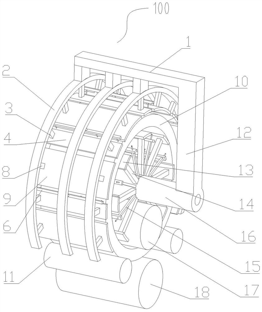
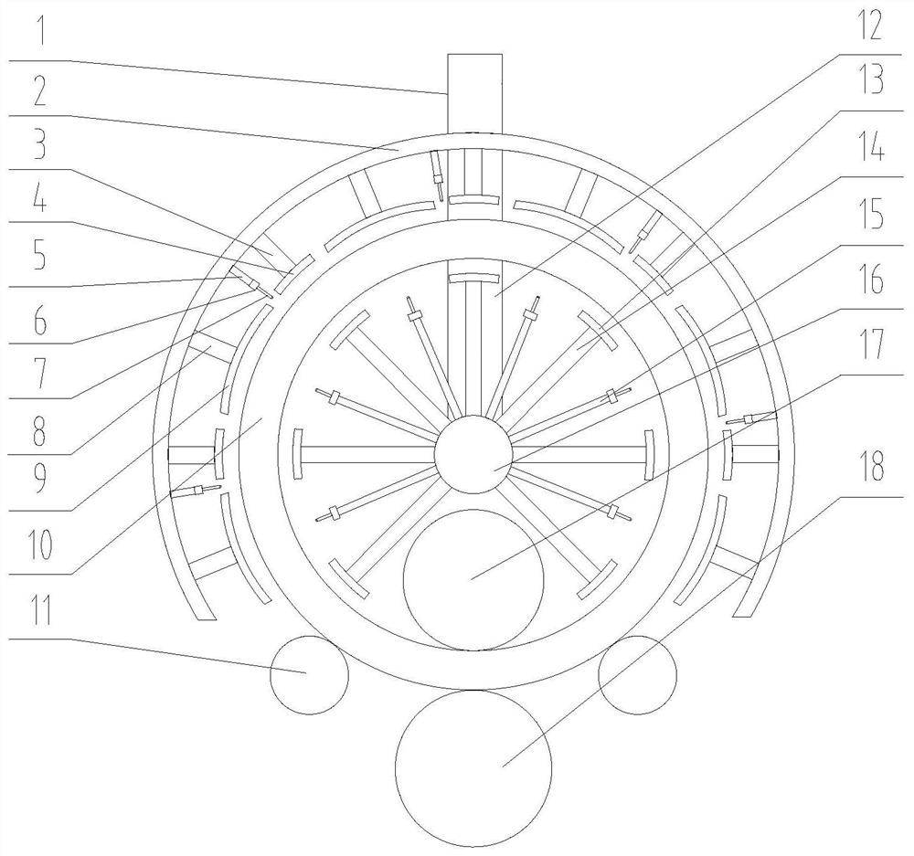
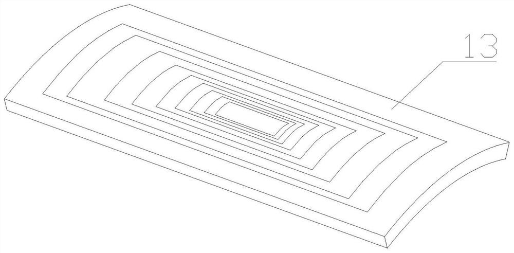
[0028] refer to Figure 1-Figure 5 As shown, the present embod...


PUM

PropertyMeasurementUnit
diameteraaaaaaaaaa
widthaaaaaaaaaa

Abstract

The invention discloses a shell ring heat treatment device and a using method thereof, and relates to the field of heat treatment in a steel rolling metallurgy process, the shell ring heat treatment device comprises a supporting main shaft used for being arranged in a shell ring, an outer suspension frame, a heating assembly and a cooling assembly, and the shell ring is arranged on a rolling device. The outer suspension frame is arranged outside the shell ring, and the shell ring is partially surrounded by the outer suspension frame. The heating assembly comprises an inner heating device and an outer heating device, the inner heating device and the outer heating device are used for being arranged inside and outside the shell ring respectively, the inner heating device is arranged on the supporting main shaft, and the outer heating device is arranged on the outer suspension frame. The cooling assembly comprises an inner cooling device and an outer cooling device, the inner cooling device and the outer cooling device are arranged inside and outside the shell ring respectively, the inner cooling device is arranged on the supporting main shaft, and the outer cooling device is arranged on the outer suspension frame. According to the shell ring heat treatment device, waste heat of the shell ring after hot rolling is utilized, the shell ring is subjected to heat treatment without moving the shell ring, the environmental protection performance is good, and the production efficiency is high.

Description

technical field [0001] The invention relates to the field of heat treatment in the steel rolling metallurgical process, in particular to a heat treatment device for a drum section and a method for using the same. Background technique [0002] Large barrel joints are widely used in pressure vessels such as various towers, hydrogenation reactors, and coal liquefaction plants. The strength, toughness and other properties of the barrel joint after forming, in addition to the influence of the material itself, the rolling process and heat treatment technology in the forming process of the barrel joint are the most important influencing factors. The current rolling process of large-scale barrel segments is generally hot rolling. During the rolling process, the properties of the steel can be adjusted by using the method of controlled cooling during the rolling process. Due to the general diameter of the large-scale cylinder section is 6 to 8m, the radial wall thickness is about 0.5...

Claims


Application Information

Patent Timeline
Patent Type & Authority Applications(China)
IPC IPC(8): C21D1/667C21D9/08C21D6/00
CPCC21D1/667C21D9/085C21D9/0062C21D9/0025C21D6/00C21D2211/001
Inventor 陈素文钱家敏袁星星秦红轩
Owner YANSHAN UNIV
Why Eureka
Try Eureka