A switch matrix multi-beam component and a switch matrix multi-beam extended component

A switch matrix and multi-beam technology, applied in the field of radio frequency, can solve the problems of low integration of microwave switch matrix, limit the application range of switch matrix, complex system redundancy, etc., reduce the number of external interfaces, reduce system complexity, The effect of low temperature

Active Publication Date: 2022-02-15
UNIV OF ELECTRONICS SCI & TECH OF CHINA
View PDF8 Cites 0 Cited by
  • Summary
  • Abstract
  • Description
  • Claims
  • Application Information

AI Technical Summary

Problems solved by technology

[0003] The existing microwave switch matrix is ​​not highly integrated, the system is complex, redundant and bulky, which limits the application range of the switch matrix

Method used


Image

  • A switch matrix multi-beam component and a switch matrix multi-beam extended component
  • A switch matrix multi-beam component and a switch matrix multi-beam extended component
  • A switch matrix multi-beam component and a switch matrix multi-beam extended component

Examples


Embodiment 1

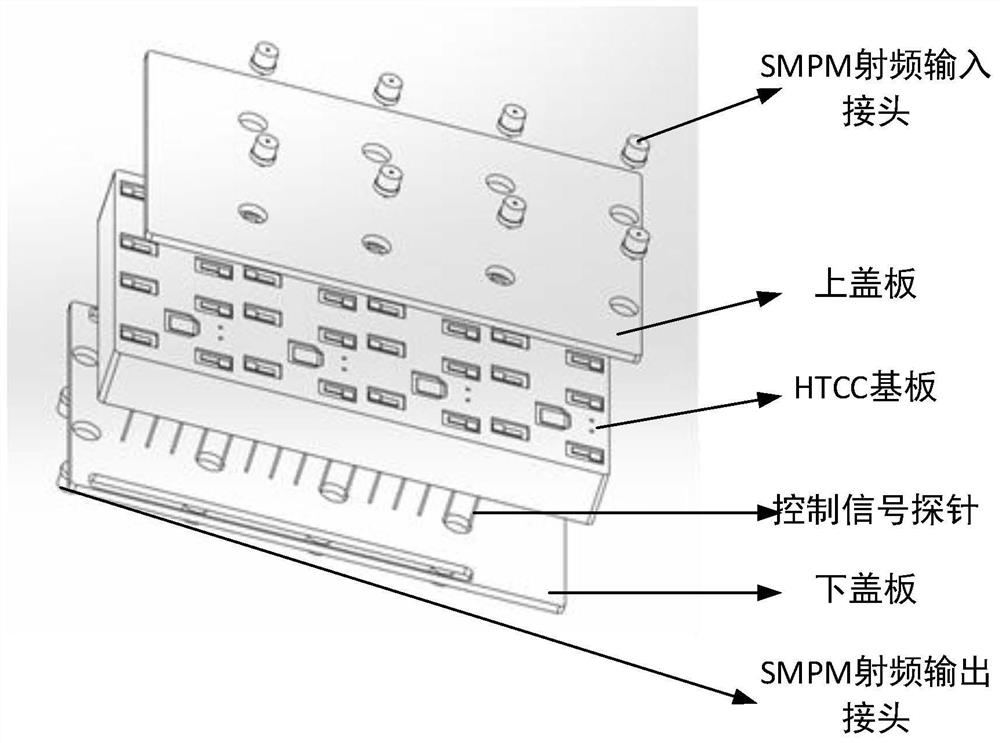
[0030] Such as figure 1 As shown, this embodiment provides an 8×8 tile-type switch matrix multi-beam component (tile type means that chips are divided into functions and stacked horizontally on the substrate and assembled vertically, that is, one functional area per layer), including the above The top cover with 8 sub-Miniature Push-on Micro (SMPM) RF input connectors, the HTCC (High- temperature co-fired ceramics, high temperature co-fired ceramics) substrate, lower cover with 8 ultra-miniature push-in connector RF output connectors;

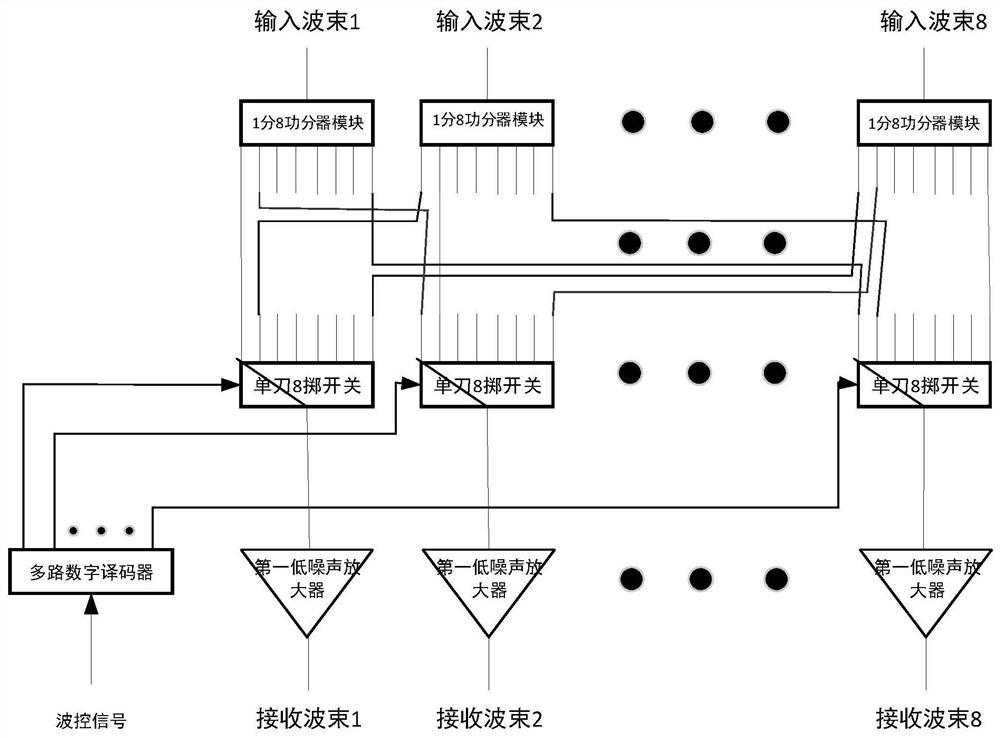
[0031] The HTCC substrate containing the tile-type switch matrix circuit includes 8 one-to-8 power divider modules on the top layer, 8 single-pole 8-throw switches on the bottom layer, 8 low-noise amplifiers, a multi-channel digital decoder and Two rows of control signal probes, and a multilayer structure radio frequency interconnection layer between the top layer and the bottom layer, the multilayer structure radio frequency interconnection l...

Embodiment 2

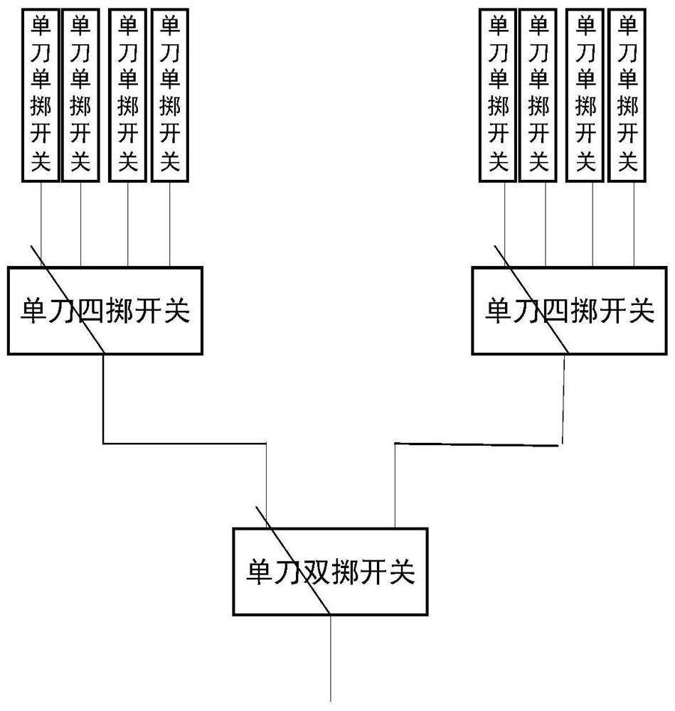
[0041] This embodiment provides an HTCC-based 2×4 tile-type switch matrix multi-beam component, which includes an upper cover plate with 2 SMPM RF input connectors arranged in sequence from top to bottom, including a 2×4 tile-type The HTCC substrate of the switch matrix circuit, the lower cover with 4 SMPM RF output connectors; the HTCC substrate containing the 2×4 tile switch matrix circuit is layered and laid out using the HTCC packaging process, including the 2 on the top layer A one-to-four power divider module, four single-pole double-throw switches located on the bottom layer, four first low-noise amplifiers, a multi-channel digital decoder and two rows of control signal probes, and the top and bottom layers between the A radio frequency interconnection layer with a multilayer structure; the radio frequency interconnection layer with a multilayer structure implements beam signal transmission through multilayer radio frequency wiring.

[0042] The working flow chart of th...

Embodiment 3

[0046] This embodiment provides an HTCC-based 16×16 tile-type switch matrix multi-beam expansion component, including an upper cover with 16 SMPM RF input connectors arranged sequentially from top to bottom, including 16 one-point HTCC substrate of two power dividers, copper-molybdenum-copper upper substrate with fur buttons, HTCC substrate array with tile switch matrix circuit, copper-molybdenum-copper lower substrate with fur buttons, 16 SPDT switches HTCC substrate, a lower cover plate with 16 SMPM RF output connectors, the HTCC substrate containing single-pole double-throw switches also contains the first multi-channel digital decoder and two rows of control signal probes; the tile-type The total number of input beams of the HTCC substrate array of the switch matrix circuit is 32;

[0047] The HTCC substrate array containing the tile-type switch matrix circuit is composed of 4 HTCC substrates containing the 8×8 tile-type switch matrix circuit obtained in Embodiment 1, and ...


PUM


Abstract

The invention discloses a switch matrix multi-beam assembly. The output beams of the radio frequency input joints of the 1st, 2nd, ..., N ultra-miniature push-in connectors are respectively connected to the 1st, 2nd, ..., N one-point-M power dividers. The input terminals of the modules are connected, and the one-M power divider module divides the received beam into M sub-channels to obtain M beam signals; the M beam signals of the One-M power divider module are respectively input to M single-pole N-throw switches Any throw of each single-pole N-throw switch, the single-pole N-throw switch is connected to the multi-channel digital decoder, and the opening and closing of the single-pole N-throw switch is controlled by the multi-channel digital decoder; each single-pole N-throw switch is respectively A low-noise amplifier is connected, and any beam signal gated by the single-pole N-throw switch is amplified by the low-noise amplifier to obtain a receiving beam, and finally M independently controllable receiving beams are obtained. The invention adopts a point-to-multiple control mode, so that one receiving beam can be switched to any input beam, and then multiple independent receiving beams can be obtained.

Description

technical field [0001] The invention belongs to the field of radio frequency technology, in particular to a switch matrix multi-beam component and a switch matrix multi-beam expansion component. Background technique [0002] Multi-beam phased array radar refers to the radar using multi-beam phased array antenna. The phased array antenna used is composed of multiple antenna units, which can form multiple independent transmitting or receiving beams. Its superior multi-beam forming capability has It helps to improve radar detection performance, radar data rate, radar anti-jamming capability and survivability, and plays a huge role in the fields of modern communication technology, electronic warfare, information warfare and radio navigation. Its multi-beam forming is often realized by means of microwave switch matrix. For multi-channel input, multiple combinations of multiple outputs can be realized according to the needs, so that signals of different frequencies and phases can ...

Claims


Application Information

Patent Timeline
Patent Type & Authority Patents(China)
IPC IPC(8): H04B1/00H04B1/401G01S7/02
CPCH04B1/006H04B1/401G01S7/023
Inventor 王志刚吴阳阳韩世宏
Owner UNIV OF ELECTRONICS SCI & TECH OF CHINA
Why Eureka
Try Eureka