Cooling fin and air cooling structure

An air-cooled structure and heat sink technology, which is applied in the construction of electrical equipment components, cooling/ventilation/heating transformation, electrical components, etc., can solve the problems of high cost and complex heat sink processing technology

Pending Publication Date: 2021-05-18
GREE ELECTRIC APPLIANCES INC
View PDF0 Cites 0 Cited by
  • Summary
  • Abstract
  • Description
  • Claims
  • Application Information

AI Technical Summary

Problems solved by technology

[0003] Therefore, the technical problem to be solved by the present invention is to overcome the defects of complex heat sink processing technology and high cost in the prior art, so as to provide a heat sink that can reduce processing difficulty and production cost
[0004] Another technical problem to be solved by the present invention is to overcome the defects of complex heat sink processing technology and high cost in the prior art, so as to provide an air-cooled structure that can reduce processing difficulty and production cost

Method used


Image

  • Cooling fin and air cooling structure
  • Cooling fin and air cooling structure
  • Cooling fin and air cooling structure

Examples


Embodiment 1

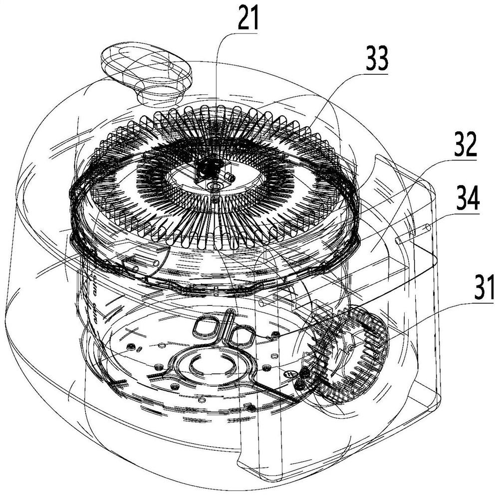
[0057]CombineFigure 1 - Figure 14 As shown, the air-cooled structure provided in this embodiment includes:

[0058]Availability 32;

[0059]The fan 31 is disposed at the first end of the air passage 32;

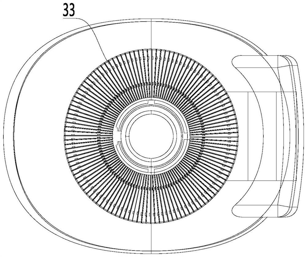
[0060]The heat sink assembly 33 is disposed at the second end of the airway 32 and communicates with the fan 31 via the wind channel 32, and the heat sink assembly 33 is adapted to contact with the heat dissipation structure;

[0061]The first end and the second end of the air passage 32 are respectively provided with the air outlet 323 and the air outlet 21, wherein the air port 323 is disposed at a relative lower end position of the exhaust port 21 in the heavier direction.

[0062]The air-cooling structure provided in this embodiment is in contact with the heat sink assembly 33 with the heat transfer structure to be dissipated, and the fan 31 is turned on with the heat sink assembly 33, so that the fan 31 blows the air from the air outlet 323 to the outlet In the process of passing the heat si...

Embodiment 2

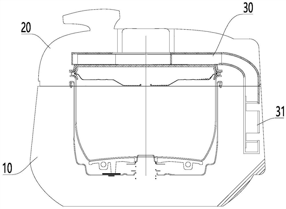
[0087]CombineFigure 1 - Figure 3 As shown, this embodiment provides a pressure 煲, including:

[0088]Body 10;

[0089]Covered cover 20, the hockey cover 20 is attached to the hinge body 10 by the hinge shaft 34; and

[0090]The air cooling structure as described above is described above.

[0091]The pressure 煲 provided in this embodiment is by using the air-cooling structure, solve the pressure cooker fast cooling and relief opening problem, enhance the user experience, and can reduce the opening time by rapid pressure, reduce the opening time, reducing the actual pressure of food, and the cooking time is long. The situation, shorten the gap between the actual cooking time and the setting cooking time, and further guarantee the consistency of the cooking mouth, avoid affecting the taste.

[0092]Preferably, the air-cooling structure is provided on the pressure cooker, which can quickly relieve the pressure, reduce the environmental contamination or even burns of the user who may be self-reliant.

[0...

Embodiment 3

[0105]CombineFigure 8 - Figure 13 As shown, the heat sink provided in this embodiment includes:

[0106]Base plate 45;

[0107]The support rib 41 is extended from the surface of the bottom plate 45 toward the direction away from the bottom plate 45;

[0108]The first fitting member 42 and the second fitting fitting 43, the first fitting member 42 or the second fitting fitting 43 is adapted to the second assembly 43 or the first assembly 42 on the side of the sink adjacent to another. Take the card connection.

[0109]The heat sink is achieved by assembling the first fitting member 42 and the second fitting fitting 43 on the heat sink, and the adjacent two sink can be assembled by the first fitting fitting 42 and the second assembly 43. The combination is convenient for manufacturing the heat sink using a mass production form, and is assembled, and the structural form of a plurality of the heat sinks is exactly the same, and there is no need to find a suitable assembly in the assembly, speed ass...


PUM


Abstract

The invention relates to the technical field of cooling devices, in particular to a cooling fin and an air cooling structure. The cooling fin includes: a base plate; supporting ribs formed by extending from the surface of the bottom plate to the direction far away from the bottom plate; and a first assembly part or a second assembly part which is suitable for being connected with the second assembly part or the first assembly part on another adjacent cooling fin in a clamping mode. According to the cooling fin, the heat dissipation area can be increased, forced air cooling resistance can be reduced, the heat dissipation amount is further increased, the cooling fin can be combined and assembled in an end-to-end connection mode, an air cooling heat dissipation channel can be conveniently formed, and the machining difficulty of an integral radiator is reduced.

Description

Technical field[0001]The present invention relates to the technical field of heat sink, and more particularly to a heat sink and a air cooling structure.Background technique[0002]The pressure cooker is an indispensable cooking instrument that modern fast-paced life, which usually has a fast cooking function, pressurized to the food seal, from increasing its cooking temperature, shortening the cooking time; but after the pressure cooking work, due to the pot The pressure is higher than atmospheric pressure, and the user cannot immediately open the food, especially the soup, fluid or viscous food. Since it is not possible to directly cool, natural cooling requires a longer waiting time, boiled porridge as an example, boiled porridge cooking When used, it is about 35 minutes, and the user's natural cooling time is as high as 25 minutes, the waiting time is long, and the user experience is poor. To this end, by providing a heat sink on the pressure cork, it can increase the heat dissipa...

Claims


Application Information

Patent Timeline
Patent Type & Authority Applications(China)
IPC IPC(8): H05K7/20
CPCH05K7/20136H05K7/20409
Inventor 胡玉新陈崇得孔进喜张力文
Owner GREE ELECTRIC APPLIANCES INC
Why Eureka
Try Eureka