
Method and test system for testing a device under test

A technology of the equipment under test and test system, which is applied in the direction of transmission system, measuring device, and measuring electrical variables, etc., and can solve problems such as high cost and long time

Pending Publication Date: 2021-08-24
ROHDE & SCHWARZ GMBH & CO KG
View PDF7 Cites 0 Cited by
  • Summary
  • Abstract
  • Description
  • Claims
  • Application Information

AI Technical Summary

Problems solved by technology

[0003] However, each test takes a long time because a continuous wave signal is used to test port matching, resulting in individual frequency sweeps of the test signal
Furthermore, the device under test must then be placed on two different test benches, which in turn leads to higher costs due to different test benches and more work

Method used


Image

  • Method and test system for testing a device under test
  • Method and test system for testing a device under test

Examples


Embodiment Construction

[0048] The detailed description, set forth below in conjunction with the accompanying drawings, in which like numerals refer to like elements, is intended as a description of various embodiments of the disclosed subject matter and is not intended to represent the only embodiment. Each embodiment described in this disclosure is provided by way of example or illustration only, and should not be construed as preferred or superior to other embodiments. The illustrative examples provided herein are not intended to be exhaustive or to limit claimed subject matter to the precise forms disclosed. The illustrative examples provided herein are not intended to be exhaustive or to limit claimed subject matter to the precise forms disclosed. For the purposes of this disclosure, the phrase "at least one of A, B, and C" means, for example, (A), (B), (C), (A and B), (A and C), (B and C ) or (A, B and C), when listing more than three elements includes all other possible permutations. In othe...


PUM


Abstract

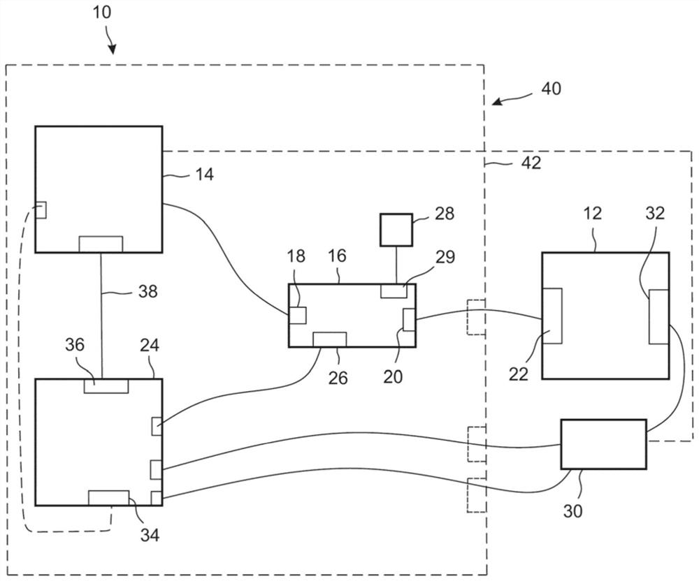
A method for testing a device under test (12) by using a test system (10) is disclosed. The method comprises: generating a wideband modulated signal; forwarding the wideband modulated signal to an input (22) of a device under test (12); separating an electromagnetic wave reflected at the input by the directional element (16); forwarding the reflected electromagnetic wave to a vector signal analyzer (24); processing a reference signal associated with the wideband modulated signal; and determining a channel response by taking the reference signal and at least one scattering parameter of the device under test (12) into account, wherein the scattering parameter depends on the reflected electromagnetic wave. Further, the present disclosure relates to a test system (10).

Description

technical field [0001] The invention relates to a method for testing a device under test by using a test system. Further, the invention relates to a test system for testing a device under test. Background technique [0002] Today, many electronic devices that process electromagnetic signals must be tested for different characteristics. Therefore, at least two different test benches are required to perform these different tests. For example, the first test bench includes a vector network analyzer (vector network analyzer, VNA), which is used to measure the port matching of the corresponding device, that is, measure the corresponding port matching parameters of the device under test. The port matching measurement is usually done by a method based on a continuous wave (continuous wave, CW) signal. Moreover, the second test bench can be used to test corresponding equipment, which includes a vector signal generator (vector signal generator, VSG) and a vector signal analyzer (v...

Claims


Application Information

Patent Timeline
IPC IPC(8): H04B17/15H04B17/29H04B17/309H04B17/354
CPCH04B17/354H04B17/309H04B17/29H04B17/15H04B17/24H04B17/345G01R19/06G01R27/32G01R27/28H04B17/0085
Inventor 沃尔夫冈·德莱塞亚历山大·罗斯弗洛里安·拉米安
Owner ROHDE & SCHWARZ GMBH & CO KG
Learn More