Electrolytic machining device and machining method thereof

A processing device and electrolyte technology, applied in electric processing equipment, electrochemical processing equipment, auxiliary devices, etc., can solve the problems of electrolyte flow rate loss, poor processing quality, low efficiency, etc., to increase flow rate and improve processing efficiency. and processing quality

Active Publication Date: 2021-08-27
GUANGDONG UNIV OF TECH
View PDF6 Cites 5 Cited by
  • Summary
  • Abstract
  • Description
  • Claims
  • Application Information

AI Technical Summary

Problems solved by technology

In this scheme, the electrolyte enters the inner cavity of the workpiece through the bottom of the machining shaft. After filling the inner cavity, the workpiece acts as an electrolytic anode, and the

Method used


Image

  • Electrolytic machining device and machining method thereof
  • Electrolytic machining device and machining method thereof
  • Electrolytic machining device and machining method thereof

Examples


Embodiment 1

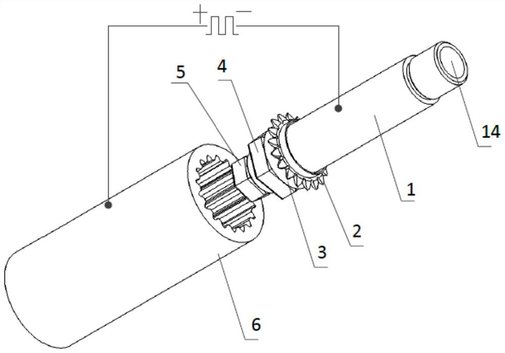
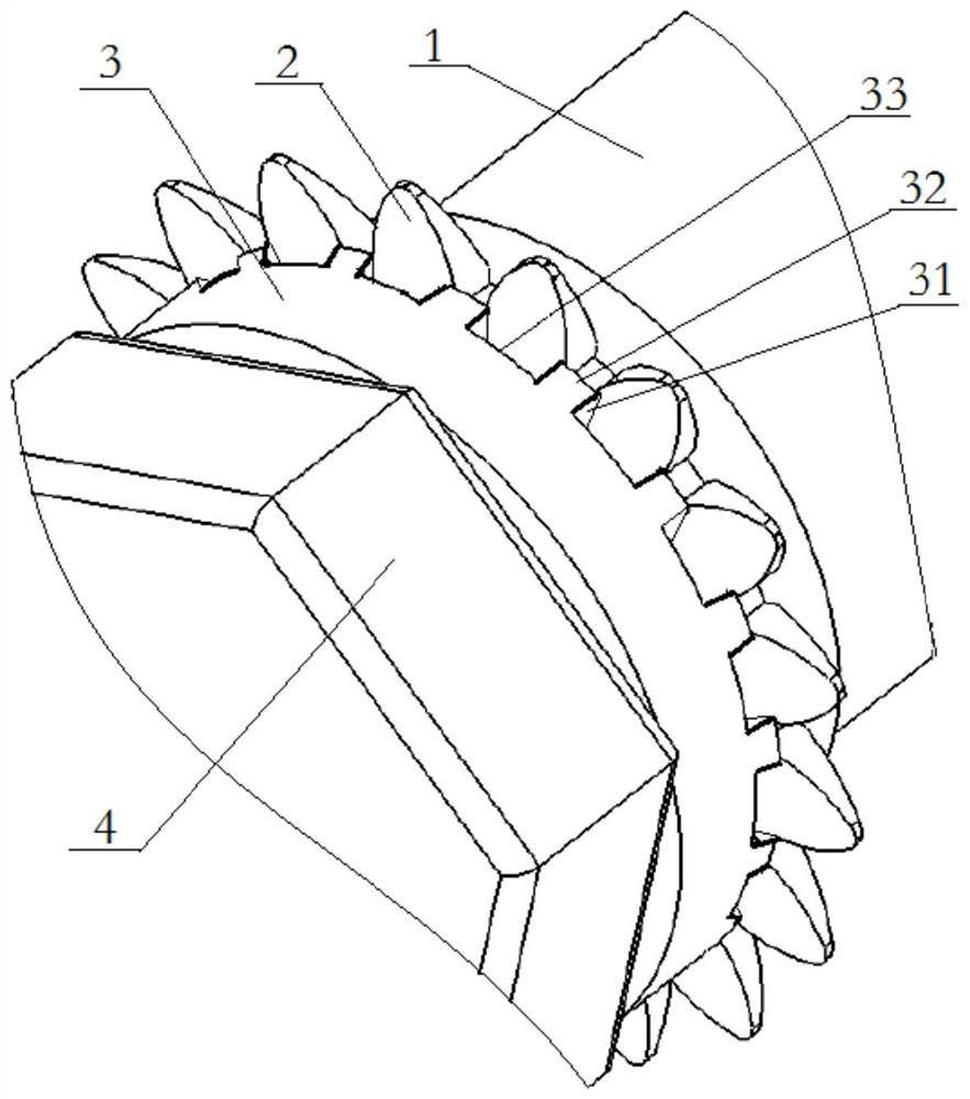
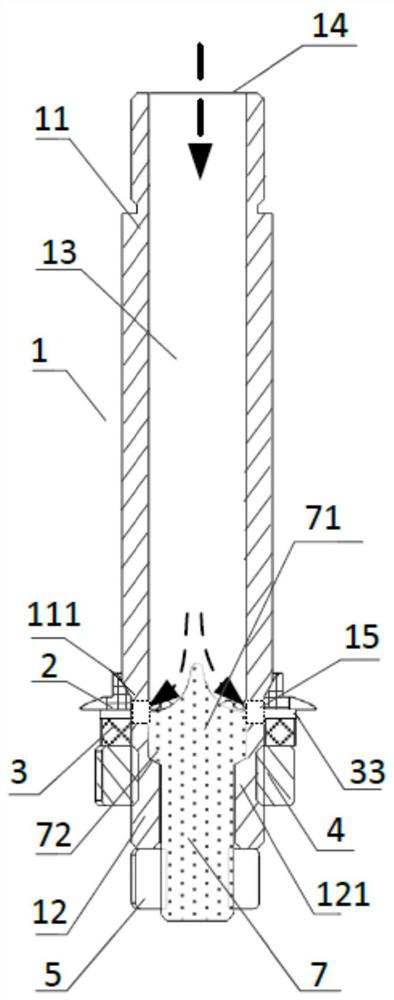
[0035] Such as Figure 1 to Figure 3 As shown, an electrolytic processing device includes a power supply and a cathode guide rod 1. The cathode guide rod 1 is provided with a hollow cavity 13 for flowing electrolyte, and one end of the cathode guide rod 1 is provided with a liquid inlet connected to the hollow cavity 13. 14, the other end of the cathode guide rod 1 is sealed, the outer wall of the cathode guide rod 1 is provided with a tool electrode 2 and a stop ring 3, the tool electrode 2 and the stop ring 3 are connected and set, and there is a connection between the tool electrode 2 and the stop ring 3 A plurality of liquid injection ports 33 communicated with the hollow cavity 13 , the negative pole of the power supply is connected to the cathode guide rod 1 , and the positive pole of the power supply is connected to the workpiece 6 .

[0036] In the above-mentioned electrolytic processing device, the electrolyte is passed into the hollow cavity 13 from the liquid inlet ...

Embodiment 2

[0045] A processing method for an electrolytic machining device as described in Embodiment 1, comprising the following steps:

[0046] S1: Position the assembled tool electrode 2 and the workpiece 6 for tool alignment;

[0047] S2: Connect the tool electrode 2 to the negative pole of the pulse power supply, and connect the workpiece 6 to the positive pole of the pulse power supply;

[0048] S3: The electrolyte is passed from the liquid inlet 14 to the cathode guide rod 1, and the electrolyte is directly sprayed from the liquid injection port 33 to the processing area between the tool electrode 2 and the workpiece 6;

[0049] S4: Turn on the pulse power supply, make the cathode guide rod 1 feed along the axial direction of the workpiece 6, and realize one-time molding processing of the workpiece 6 .

[0050] In the above-mentioned electrolytic machining method, the electrolyte flows to the liquid injection port 33 through the liquid outlet 15, and finally directly sprays the p...


PUM


Abstract

The invention relates to the technical field of machine manufacturing non-traditional machining, in particular to an electrolytic machining device and a machining method thereof. The electrolytic machining device comprises a power source and a cathode guide rod, the cathode guide rod is provided with a hollow cavity for allowing an electrolyte to flow, a liquid inlet communicating with the hollow cavity is formed in one end of the cathode guide rod, and the other end of the cathode guide rod is sealed. A tool electrode and a baffle ring are arranged on the outer wall of the cathode guide rod, the tool electrode is connected with the baffle ring, multiple liquid spraying openings communicating with the hollow cavity are formed between the tool electrode and the baffle ring, a negative electrode of the power source is connected with the cathode guide rod, and a positive electrode of the power source is connected with a workpiece. In the electrolytic machining device, the electrolyte can only be directly sprayed to a machining area from the liquid spraying openings between the tool electrode and the baffle ring, the flow speed of the electrolyte in the machining area is increased, the machining efficiency and the machining quality of electrolytic machining are greatly improved, and the tool electrode can be designed into different shapes according to needs so as to machine inner gear grooves, key grooves and other workpieces in different shapes.

Description

technical field [0001] The invention relates to the technical field of special machining in mechanical manufacturing, and more specifically, to an electrolytic machining device and a machining method thereof. Background technique [0002] Internal gear transmission has a series of advantages such as compact structure and high transmission efficiency, so it is widely used in mechanical transmission devices. However, due to the limitation of the structure of the internal gear itself, most internal gears can only be processed by traditional processing technology. The processing accuracy of traditional processing technology often fails to meet the requirements, which directly affects the quality of gear transmission. The traditional processing techniques of internal gears include gear shaping and broaching. [0003] Gear shaper processing is to process gears according to the generation method. The gear shaper cutter and the gear to be processed move according to the meshing rel...

Claims


Application Information

Patent Timeline
IPC IPC(8): B23H3/00B23H11/00
CPCB23H3/00B23H11/00
Inventor 张永俊张传运陈晓磊郭锦辉蒋庆财
Owner GUANGDONG UNIV OF TECH
Why Eureka
Try Eureka