Tail gas emission structure and reduction furnace

A tail gas emission and reduction furnace technology, applied in chemical instruments and methods, inorganic chemistry, non-metallic elements, etc., can solve problems affecting the quality of polysilicon production, uneven gas pressure and flow, and unstable pressure, flow field, and temperature field of the reduction furnace And other issues

Pending Publication Date: 2021-08-27
新疆硅基新材料创新中心有限公司 +1
View PDF13 Cites 0 Cited by
  • Summary
  • Abstract
  • Description
  • Claims
  • Application Information

AI Technical Summary

Problems solved by technology

[0003] The purpose of the embodiments of the present application is to provide a tail gas discharge structure and a reduction furnace to solve the uneven pressure and flow rate of the gas in the tail gas pipe of the reduction furnace, resulting in instability of the pressure, flow field, and temperature field in the reduction furnace, which affects the formation of polysilicon quality problem

Method used


Image

  • Tail gas emission structure and reduction furnace
  • Tail gas emission structure and reduction furnace
  • Tail gas emission structure and reduction furnace

Examples


Embodiment Construction

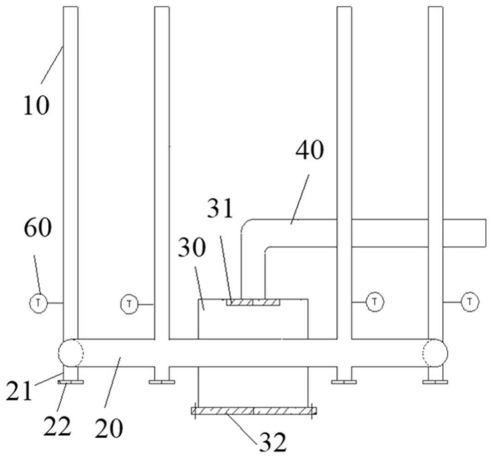
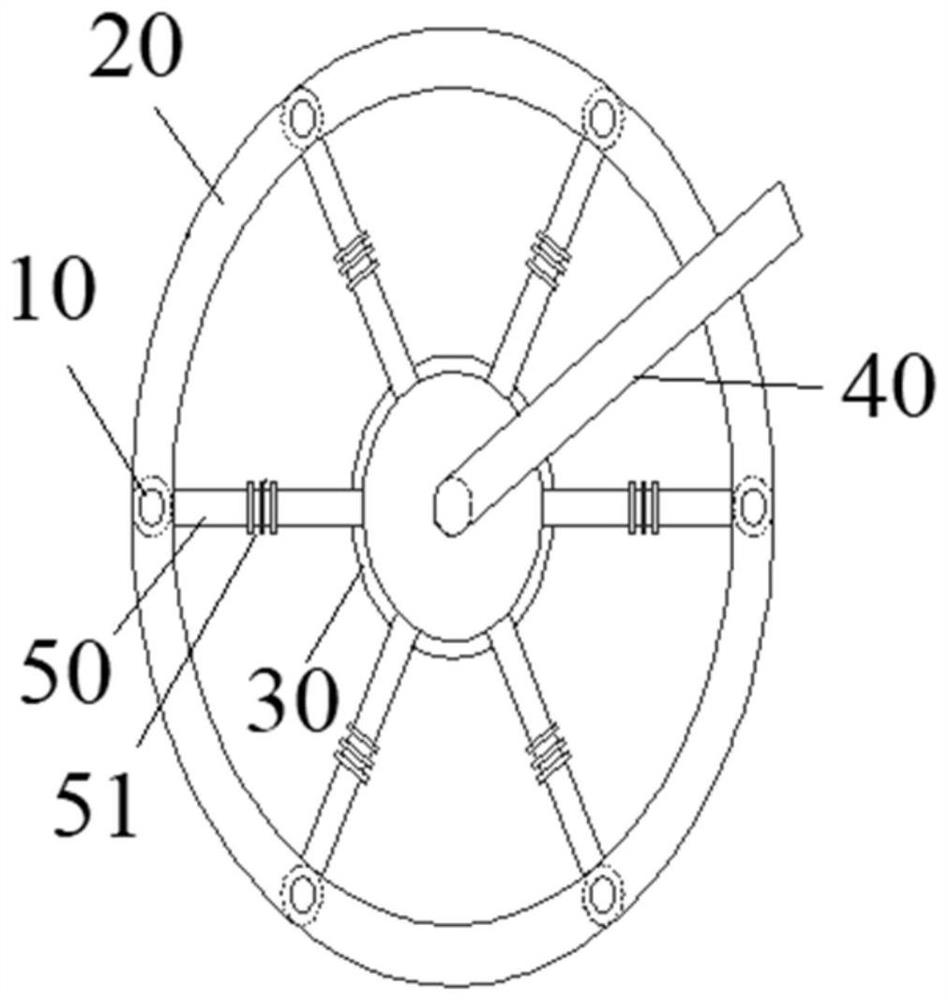
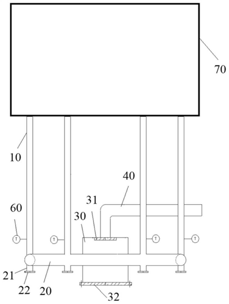
[0039] The following will clearly and completely describe the technical solutions in the embodiments of the present application with reference to the drawings in the embodiments of the present application. Obviously, the described embodiments are part of the embodiments of the present application, not all of them. Based on the embodiments in this application, all other embodiments obtained by persons of ordinary skill in the art without creative efforts fall within the protection scope of this application.

[0040] The terms "first", "second" and the like in the specification and claims of the present application are used to distinguish similar objects, and are not used to describe a specific sequence or sequence. It is to be understood that the data so used are interchangeable under appropriate circumstances such that the embodiments of the application can be practiced in sequences other than those illustrated or described herein. In addition, "and / or" in the specification an...


PUM


Abstract

The invention discloses a tail gas emission structure and a reduction furnace. The tail gas emission structure comprises a plurality of tail gas branch pipes, the first end of each tail gas branch pipe communicates with an annular pipe, and the first ends of the multiple tail gas branch pipes are arranged in the circumferential direction of the annular pipe at intervals. The annular pipe communicates with a balance box. The first end of a tail gas mother pipe communicates with the balance box. The tail gas branch pipes communicate with exhaust holes in the bottom of a reduction furnace, gas in the reduction furnace enters the tail gas branch pipes through the exhaust holes, tail gas in the tail gas branch pipes enters the annular pipe, tail gas in different tail gas branch pipes can be balanced in the annular pipe, and the tail gas in the annular pipe enters the balance box to be balanced, so that the pressure of the gas is more uniform, and then gas in the balance box is exhausted through the tail gas mother pipe. The gas flow in each tail gas branch pipe is balanced through the annular pipe and the balance box, so that the silicon formation condition and the silicon slag cleaning frequency in the tail gas branch pipes are reduced, the tail gas emission is kept uniform and stable, and the pressure, the flow field and the temperature field in the reduction furnace are more stable.

Description

technical field [0001] The application belongs to the technical field of polysilicon, and in particular relates to a tail gas discharge structure and a reduction furnace. Background technique [0002] Polysilicon is the main raw material for manufacturing integrated circuits and solar cells. The production of polysilicon mainly uses the improved Siemens method. Raw materials such as chlorosilane and hydrogen are sent into the reduction furnace to produce polysilicon by chemical vapor deposition (CVD) reaction on the silicon rods. During the production process, in order to ensure high production efficiency in the reduction furnace, To increase its deposition rate on the surface of the silicon rod, the raw material gas is continuously injected through the nozzle, and at the same time, the low-concentration chlorosilane after the reaction and the by-products during the reaction are continuously discharged through the tail gas port. When the tail gas flows through the tail gas ...

Claims


Application Information

Patent Timeline
Patent Type & Authority Applications(China)
IPC IPC(8): C01B33/035
CPCC01B33/035
Inventor 冯留建吴万里张霞飞范协诚王文银波孙运德
Owner 新疆硅基新材料创新中心有限公司
Why Eureka
Try Eureka