High-density read-only optical disk

A high-density, optical disc technology, applied in the direction of optical replication, optical record carrier, optical recording/reproduction, etc., can solve problems such as data reading errors

Inactive Publication Date: 2003-12-31
SAMSUNG ELECTRONICS CO LTD
View PDF0 Cites 0 Cited by
  • Summary
  • Abstract
  • Description
  • Claims
  • Application Information

AI Technical Summary

Problems solved by technology

Therefore, data recorded on high-capacity optical discs with a p value of 0.6 or 0.5 μm cannot be tracked with first-generation DVD players having predetermined λ and NA values
[0010] Even though tracking is possible, data is read from adjacent tracks, which introduces noise and data reading errors known as crosstalk

Method used


Image

  • High-density read-only optical disk
  • High-density read-only optical disk
  • High-density read-only optical disk

Examples


Embodiment Construction

[0020] Preferred embodiments of the present invention will be described below with reference to the accompanying drawings. It should be noted that the same elements are denoted by the same reference numerals in the drawings, and descriptions of generally known functions and structures related to the present invention will not be repeated unless it may mislead the main matters of the present invention.

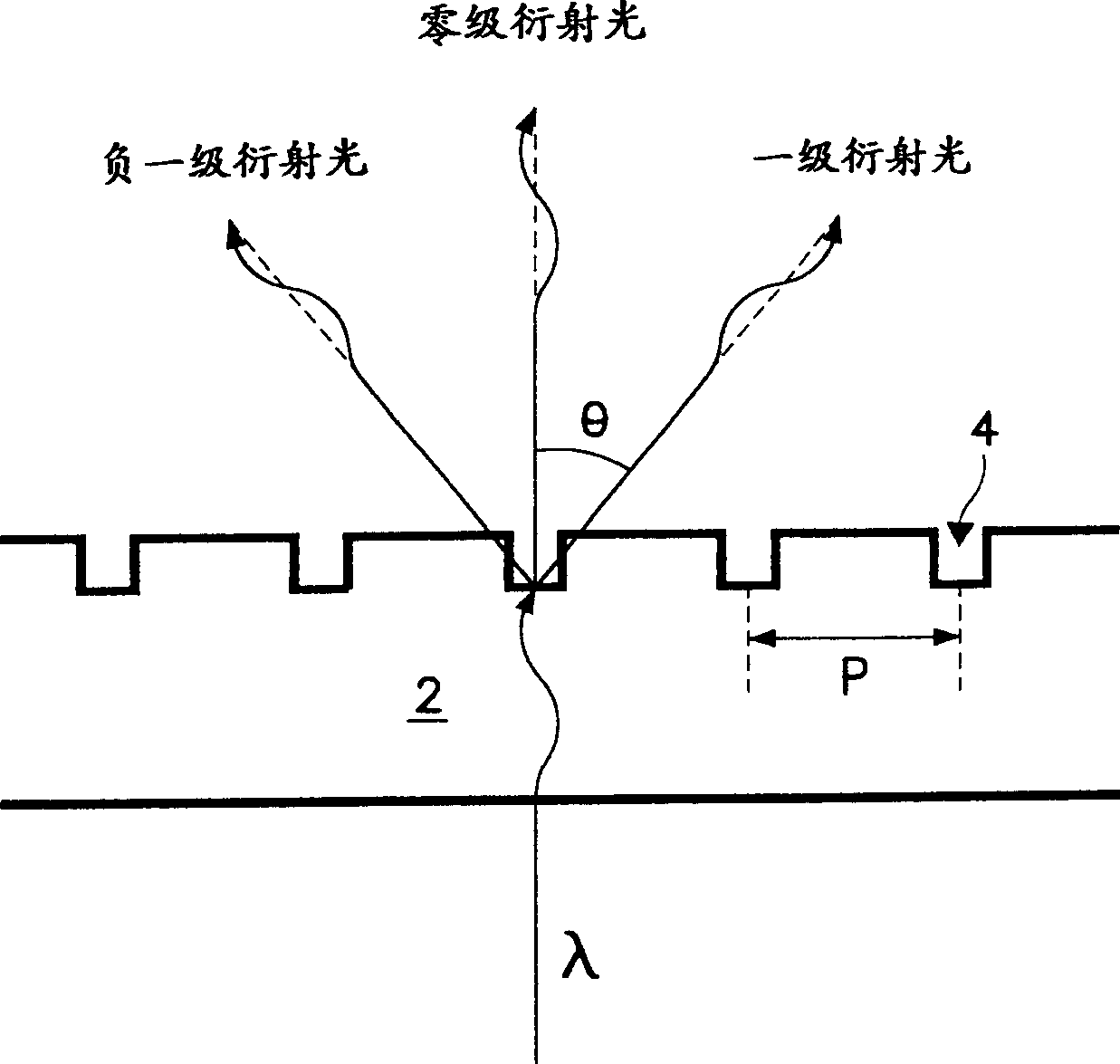
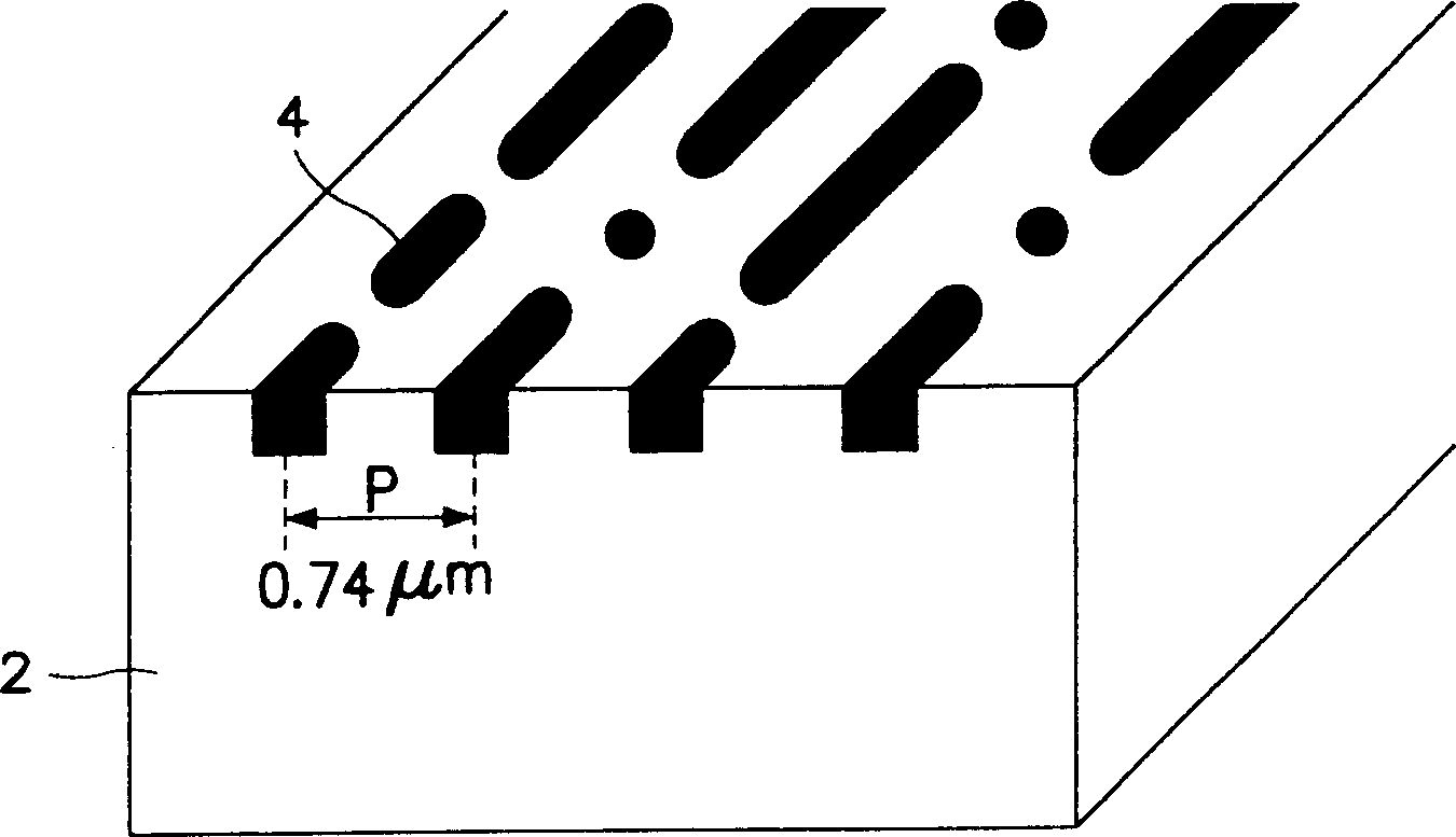
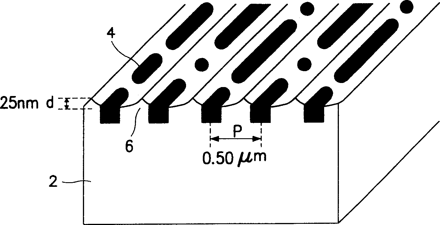
[0021] image 3 A schematic track structure of a DVD according to an embodiment of the present invention is shown. Such as image 3 As shown, the data recording capacity of the DVD is improved by reducing the track pitch from 0.74 μm to 0.5 μm. In order to solve the tracking servo problem and crosstalk problem encountered when reading a DVD with a narrower 0.5 μm track pitch using a prior art DVD player, a wave-shaped groove 6 is formed in each track of the DVD, And data pits 4 are formed in the grooves 6 . The wavy groove 6 is continuously formed along the track so as to r...


PUM

PropertyMeasurementUnit
thicknessaaaaaaaaaa

Abstract

A high-density read-only optical disk. In the optical disk, plural grooves continuously forms a waveform manner along each track, providing plural information pits to the grooves and making possible to reproduce the information from the track pits which are narrower than the track pits of the optical disk having only information pits for every track.

Description

technical field [0001] The present invention relates to an optical disc system for recording digital audio and video data in the form of pits on an optical disc and reading the data with a laser beam, in particular, to a substrate having a surface structure for increasing data recording density CD-ROM. Background technique [0002] In optical recording and reading technology, data is read from an optical disc by using a laser beam according to the difference in intensity of reflected light. The intensity of the reflected light is variable, that is, the recording of data on the disc, in the case of a general CD (Compact Disc) or DVD (Digital Video Disc), is done by utilizing the optical interference between the pit and the reference plane In the case of magneto-optical disks, this recording is accomplished by changing the deflection direction of the magneto-optical recording material; in the case of phase-change optical disks, it is accomplished by the difference in the inte...

Claims


Application Information

Patent Timeline
Patent Type & Authority Patents(China)
IPC IPC(8): G11B7/007G11B7/09G11B7/24076G11B7/24079G11B7/24085
CPCG11B7/24079G11B7/24076G11B7/0938G11B7/007G11B7/261G11B2007/00709G11B2007/00754
Inventor 安荣万
Owner SAMSUNG ELECTRONICS CO LTD
Why Eureka
Try Eureka