

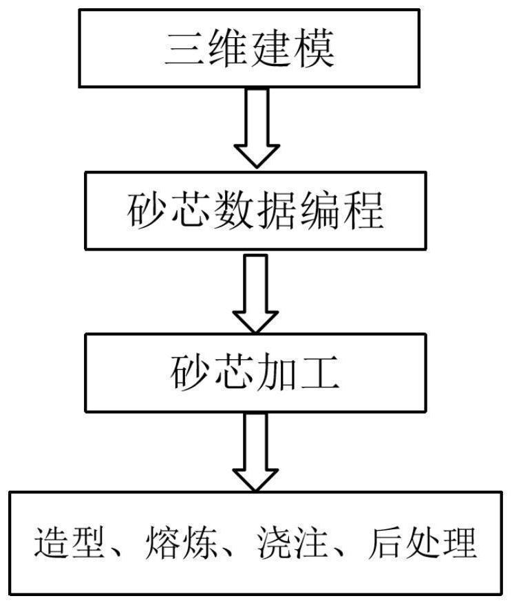
Rapid manufacturing method for impression cylinder casting
A manufacturing method and embossing roller technology, which is applied in the manufacture of tools, casting molding equipment, casting molds, etc., can solve the problems of time and labor consumption of outer molds and core boxes, high production costs, and long production cycles, so as to shorten production Cycle, production cycle shortened, the effect of accurate size
- Summary
- Abstract
- Description
- Claims
- Application Information
AI Technical Summary
Problems solved by technology
Method used
Image

Examples
Embodiment 1
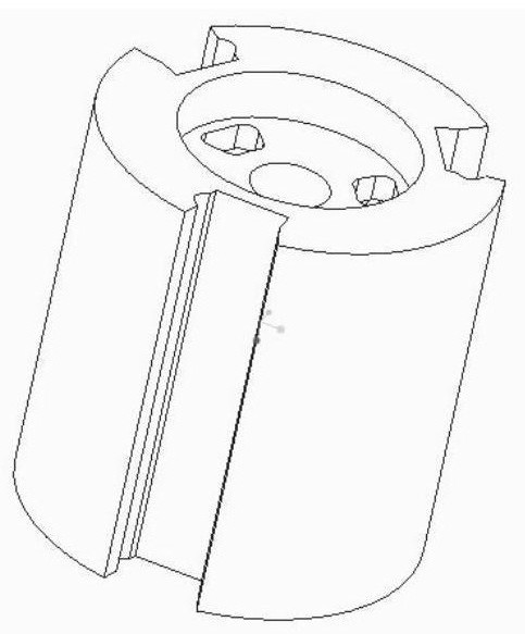
[0045] 1. According to the external dimension of the casting is Φ809×842mm and the drawing, the three-dimensional model of the casting is obtained, such as figure 2 shown.
[0046] 2. Determine the parts that can be rapidly formed according to the casting structure, and divide the parts into three parts, and number them as 1#, 2#, and 3#.
[0047] 3. Through the UG software Boolean operation, reverse the core entity to obtain the three-dimensional model of the cavity, and obtain the original structure and three-dimensional solid model of the 1#, 2#, and 3# block cores, and improve the core head according to the process 3D design.
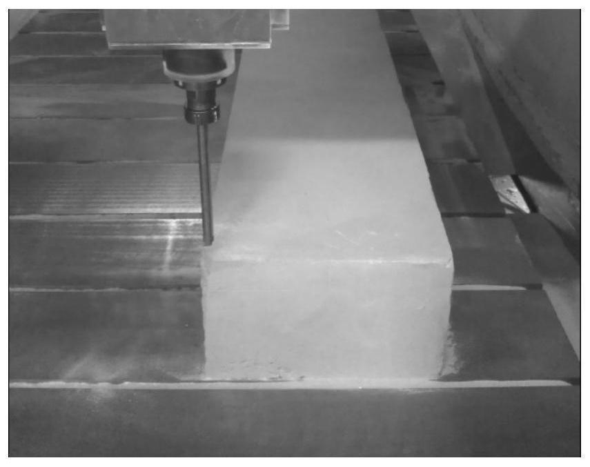
[0048] 4. According to the size of the core, apply an appropriate margin to make a cuboid sand blank. The size and quantity of the sand blank are shown in Table 1, and the technical parameters of the sand blank are shown in Table 2;
[0049] Table 1 The original size and quantity of sand blanks
[0050]
[0051] Table 2 Technical parameters o...
Embodiment 2
[0064] Qualified samples are quickly produced by using the non-pattern casting process based on CNC machining. Combined with the actual production situation of the impression cylinder, see Table 3 and Table 4 for the comparison of the manufacturing cycle and manufacturing cost between the moldless casting process based on CNC machining technology and the traditional casting process.
[0065] Table 3 Single casting manufacturing cycle
[0066]
[0067] Table 4 Single casting manufacturing cost
[0068]
[0069] It can be seen from the table that when producing a single piece, compared with the traditional casting process, the moldless casting process based on numerical control processing technology saves 35,000 yuan in cost and shortens the production cycle by about 47 days for a single person. The manufacturing cost and production cycle are mainly saved due to the adoption of casting mold manufacturing technology based on CNC machining, and the rest of the links are not...
PUM
 Abstract
Description
Claims
Application Information