Numerical control centerless grinding machine with automatic feeding function
A centerless grinding machine and automatic feeding technology, which is applied in the direction of grinding machine, grinding bed, machine tool designed for grinding the rotating surface of workpiece, etc., can solve the problems of operator and equipment contact, staff injury, etc., and reduce potential safety hazards. , The effect of improving processing and production speed and reducing costs
- Summary
- Abstract
- Description
- Claims
- Application Information
AI Technical Summary
Problems solved by technology
Method used
Image


Examples
Embodiment Construction
[0020] The following will clearly and completely describe the technical solutions in the embodiments of the present invention with reference to the accompanying drawings in the embodiments of the present invention. Obviously, the described embodiments are only some, not all, embodiments of the present invention. Based on the embodiments of the present invention, all other embodiments obtained by persons of ordinary skill in the art without making creative efforts belong to the protection scope of the present invention.
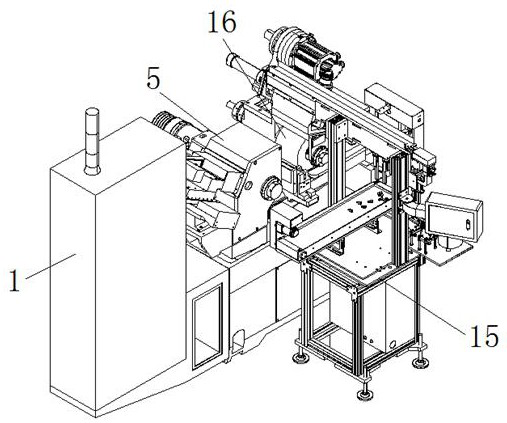
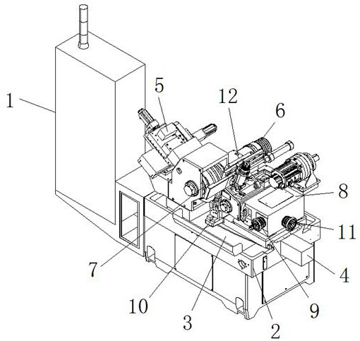
[0021] see Figure 1-4 , the present invention provides a technical solution: a CNC centerless grinding machine with automatic feeding, including an equipment frame 1, a workbench 2 is fixedly installed on the upper end of the equipment frame 1, and a chip collection groove 3 is provided on the workbench 2, and the working One end of the table 2 is movably installed with a driving box 4, and the upper end of the workbench 2 is movably installed with an install...
PUM
 Abstract
Description
Claims
Application Information