House building engineering column top steel bar drilling and planting auxiliary device

A technology of construction engineering and auxiliary devices, which is applied in the field of housing construction, and can solve problems such as multiple operating points, falling from heights, and high physical exertion

Pending Publication Date: 2021-08-31
THE FIFTH ENG CO LTD OF CHINA RAILWAY NO 10 ENG GRP
View PDF6 Cites 2 Cited by
  • Summary
  • Abstract
  • Description
  • Claims
  • Application Information

AI Technical Summary

Problems solved by technology

[0004] In order to make up for the deficiencies of the existing technology, solve the problem that there are a large number of rebars to be planted, many operating points, frequent moving of ladders or erecting of platforms, great physical exertion, increased cost of erecting platforms, and drilling at high places , it is easy to cause the problem of falling from a high place. The present invention proposes an auxiliary device for drilling and planting steel bars on the top of a building construction project.

Method used


Image

  • House building engineering column top steel bar drilling and planting auxiliary device
  • House building engineering column top steel bar drilling and planting auxiliary device
  • House building engineering column top steel bar drilling and planting auxiliary device

Examples


Embodiment 1

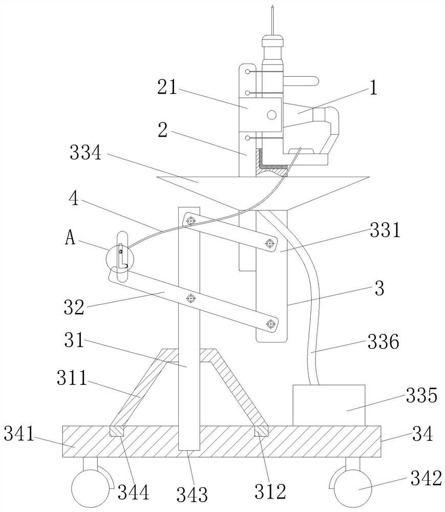
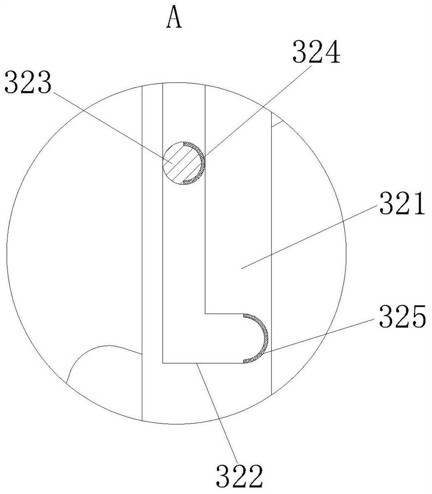
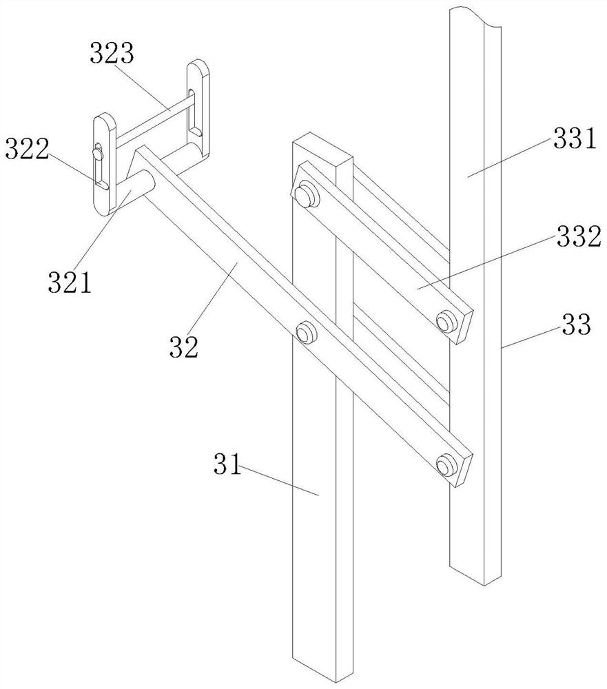
[0029] see Figure 1-6 As shown, an auxiliary device for drilling and planting steel bars at the top of a house construction project includes a drilling machine body 1, a fixed rod 2, a support assembly 3 and a pull rope 4; the fixed rod 2 is fixed on the support assembly 3 on the side wall; the drilling machine body 1 is arranged on the top of the support assembly 3, and the drilling machine body 1 is affixed to the fixing rod 2 through iron wire; the stay rope 4 passes through the drilling machine body 1, and the stay rope 4 ends partly wound on the support assembly 3; the support assembly 3 includes a column 31, a handle bar 32 and a lifting mechanism 33; a pair of the handle bars 32 are connected to the outer side wall of the column 31 by rotating pins, and are respectively located on the column 31 opposite On the two side walls of the side wall; the lifting mechanism 33 is arranged on the outer side wall of the column 31, and the lifting mechanism 33 is connected with the...

Embodiment 2

[0040] see Figure 7 As shown in Comparative Example 1, as another embodiment of the present invention, an anti-slip gasket 241 is fixedly attached to the side wall of the splint 24; the material of the anti-slip gasket 241 is rubber; The anti-slip gasket 241 is fixedly connected on the side wall of 24 to increase the friction force between the splint 24 and the contact surface of the drilling machine body 1, so that the fixing effect of the splint 24 is better.

[0041] Working principle: When drilling and planting steel bars, the drilling machine body 1 is placed in the groove 333 on the top of the dowel bar 331, and the rubber pad 337 on the inner wall of the groove 333 starts the drilling machine body 1 Buffer protection function, when the drilling machine body 1 is stuck between the two baffles 21, the threaded rod 23 is rotated, the threaded rod 23 and the threaded hole 22 are threadedly matched, and the splint 24 is gradually approached during the rotation of the thread...


PUM


Abstract

The invention belongs to the technical field of house building, and particularly relates to a house building engineering column top steel bar drilling and planting auxiliary device. The device comprises a drilling machine body, a fixing rod, a supporting assembly and a pull rope, wherein the fixing rod is fixedly connected to the side wall of the supporting assembly, the drilling machine body is arranged on the top of the supporting assembly, the end part of the pull rope is wound on the supporting assembly, the supporting assembly comprises a stand column, handle rods and a lifting mechanism, the pair of handle rods are rotationally connected to the outer side wall of the stand column by means of rotating pins and located on the two opposite side walls of the stand column correspondingly, the lifting mechanism is arranged on the outer side wall of the stand column, and the lifting mechanism is rotationally connected with the handle rods by means of rotating pins. According to the device, the drilling machine body is driven by the lifting mechanism to ascend, so that steel bar planting and drilling work is conducted, a high-altitude falling phenomenon caused by manually carrying a ladder or erecting a platform is avoided, and the safety of the drilling work is improved.

Description

technical field [0001] The invention relates to the technical field of building construction, in particular to an auxiliary device for drilling and planting steel bars on column tops of building construction projects. Background technique [0002] In housing construction projects, structural column reinforcement (bottom reinforcement, top reinforcement) is mostly constructed by planting reinforcement, and it is necessary to drill holes for the planting reinforcement before performing the reinforcement work. [0003] In the current existing technology, the traditional drilling method for planting bars is that the operator carries a drilling machine, protective glasses, and a dustproof hat, and sets up a platform or a ladder, and stands on the platform or ladder to perform drilling operations. There are many, many operating points, frequently moving ladders or building platforms, which consumes a lot of physical strength and increases the cost of building platforms, and when d...

Claims


Application Information

Patent Timeline
Patent Type & Authority Applications(China)
IPC IPC(8): B28D1/14B28D7/00B28D7/02
CPCB28D1/146B28D7/00B28D7/02
Inventor 赖卫聪吴刚杨建新冯杨李建军
Owner THE FIFTH ENG CO LTD OF CHINA RAILWAY NO 10 ENG GRP
Why Eureka
Try Eureka